Apple Cassette Interface Notes
The ACI Parser Bug
I
don't know if this is really a bug or a compromise in the design needed
to get it into 256 bytes of code space. This code is really tight
and there is really no free space to do more.
Always enter all
four characters of 16 bit hex address when entering addresses into the
ACI parser. The parser doesn't clear out preexisting addresses,
so unless you enter all four address characters, you will use whatever
was already present in memory mixed in with the new address.
EXAMPLE: to load Hamarabi enter the following
004A.00FFR 0400.0FFFR
Cassette Interface LED Operation
The
LED on the Cassette Inteface is set to light at about 1.2 volts.
This voltage is way too high, so don't expect the LED to operate
correctly on your ACI.
Cassette Interface Reliability Improvement
I
have discovered that the Apple II cassette interface is far more
reliable than the Apple 1 was. I did spice simulations of both and
quite a bit of fooling around with the actual ACI in order to see if I
could figure out the problem. The best improvement I could come up
with, was to add a low pass filter on the input. This was done by
adding a .01uF cap between the input side of the comparator and ground.
After
experimenting extensively with the ACI, I finally discovered the real
difference in the design that makes the Apple II so much more reliable.
The Apple II uses a .1uF capacitor for input coupling versus a .01uF on
the ACI. When I originally looked at this, I must have forgotten to
make this change when evaluating the designs with spice. This change
provides a lot more noise immunity in the comparator inputs.
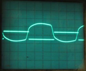
Here
is the ACI input signal with the stock .01uF input coupling capacitor.
The source of the signal is the 1HZ tone (all ones) at the front of
Wendell Sanders Hammerabi clip being played from an iPod with the
equalizer set to “treble reducer”. All signals are
displayed at .5 volts/division on this page.
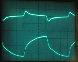
In
the image, above, the input is the bottom signal and top signal is how
it is presented to the comparator input after passing through the
capacitor. Note how the signal spikes and then returns to the value set
by the 10K resistors.
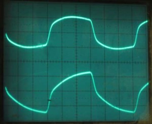
Above
is the same input and output signals with a .1uF capacitor. The signal
follows the shape of the input waveform much more closely. The bottom
trace is input signal and is the same as in the first image. The top
trace is input to comparator after passing through cap. Note how the
extra capacitance prevents the resistors from quickly returning to the
base value set by the resistors.
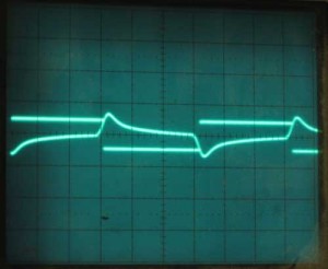
This
image shows both inputs to the comparator with the stock .01uF
capacitor. Spiky looking trace is input signal to comparator (same
signal as seen in first image). Other trace is reference signal with
hysterisis. The reference signal is pulled up and down slightly as the
comparator switches state to prevent instability. This results in the
square wave.
In the picture above, the output switches state
when input signal (more spiky looking signal) passes the level of the
reference signal as can be plainly seen in this image. The problem with
this design is the limited amount of room between the input and the
reference, any input noise with an amplitude of around .2 volts or more
may be enough to trigger a switch in output levels.
Below are
the same two inputs to the comparator with the .1uF cap. This wave form
increases noise immunity to almost a volt, about 5 times improvement
over the apple 1 stock implementation.
Unless
you are interested in maintaining complete commonality with the
original Apple 1, I highly recommend using a .1uF capacitor in your
replica cassette interface instead of the .01uF used in the original
design. Keep in mind that the folks at Apple recognized this
improvement before coming out with the Apple II, as that design
includes .1uF cap for this application.
Since I was using a
clone ACI, built with components based on the schematics, I wondered if
Apple actually shipped with .1uF caps on the ACI. I exchanged a couple
of emails with Wendell Sander. He confirmed that the schematics are
correct and the Apple ACI did indeed ship with a .01uF caps. He also
confirmed that he had independently come to the same conclusion
regarding the reliability improvement that could be attained with a
.1uF cap.
Apple recommended tape recorder
Back
in the old days, the Apple recommended tape recorder was a Panasonic
RQ2102. Believe it or not, they are still available from
Panasonic. This recorder works much better than the period Radio
Shack recorder that I was attempting to use. I highly recommend
you find a RQ2102 to go with your Apple 1.
Schematics Errors
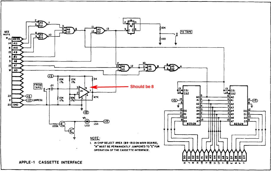
Like
usual there is an error in the schematics - this time only 1 error.
Pin 5 of the voltage comparator is identified as being connected
to +5V. Instead pin 8 is connected to +5V and pin 5 is left open.
Reliability
Even
with the RQ2102 recorder and the .1uF capacitor change don't
expect perfect operation, you'll still have to play with the volume
control and may have trouble loading programs if everything isn't
working just right.
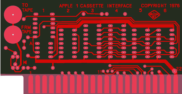
Reproduction ACI Boards
I've layed out a reproduction ACI board. The image at top of this page is artwork from this layout. My blog
details some of the steps I taken in this process.
The price is now
$100, with the exception of those who buy a Mimeo 1 kit at the same
time. Those who buy a Mimeo kit at the same time they buy an ACI card, will get the
special $75 price. This is the original price of an ACI card.
Send me Email at mike@willegal.net for ordering information.
A downloadable copy of the ACI build and operations manual
is now available for downloading. This manual contains a
reproduction of the original Apple ACI manual and an annotated listing of the firmware as appendixes.