The Enclosure

click here to go to kit information page


This 
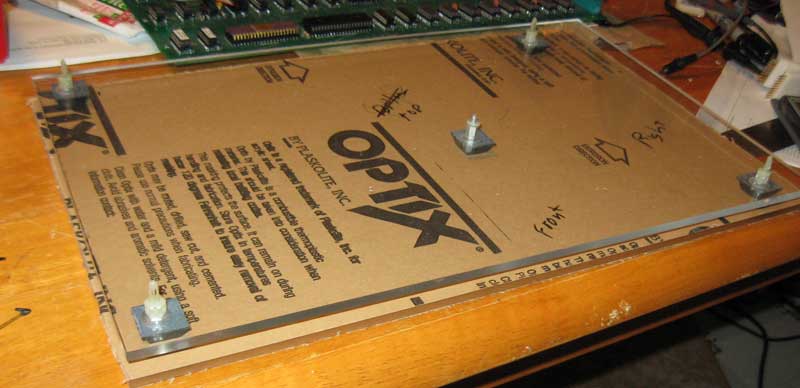
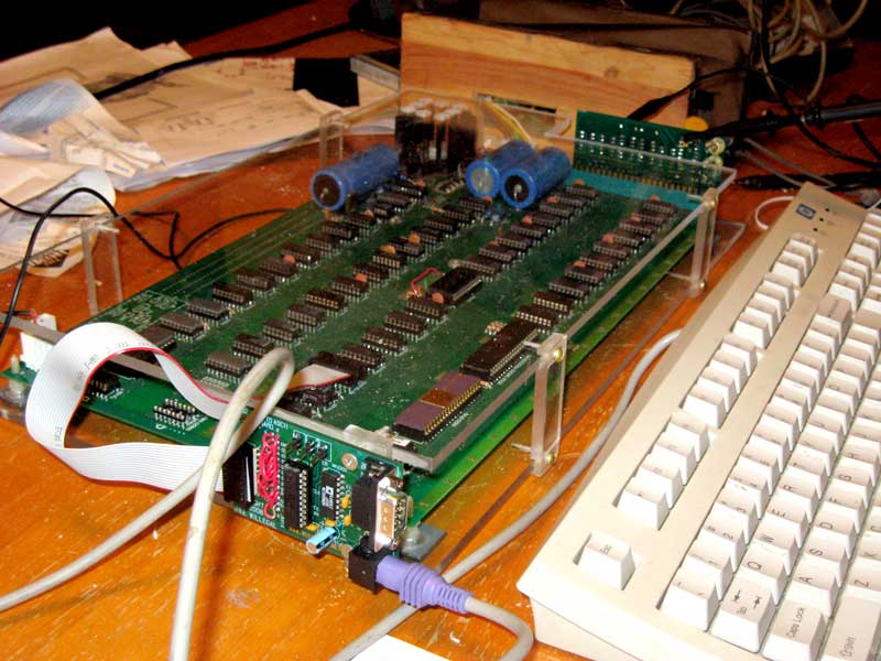
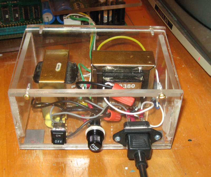
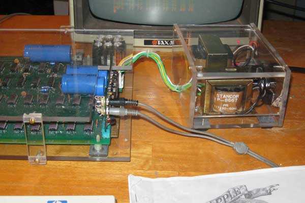
enclosure is sort of being designed on the fly.  The power entry module (transformers) will be mounted in a separate enclosure.  Material is 1/4" Plexiglas found in the remainder bin at a nearby hardware store.  Plexiglas is cut on a table saw and edges are polished with a buffer and car polish.  First thing to be built is the base.
base for enclosure

The Base

Here is the base for the enclosure.  Standoffs salvaged from an Apple II plus are mounted in holes drilled and countersunk into the base.  Rubber feet are from Radio Shack and are placed over the holes that were drilled for the standoffs. A half inch was left around the perimeter in order to allow space to mount the supports for the top. The top's overall dimensions were cut at the same time as the bottom.  It lies between the bottom and the table with protective paper still in place.

Mimeo mount on base

Mimeo mounted on the base.  The Mimeo's mounting holes are a very tight fit on the standoffs.  Be very careful when mounting the board on the standoffs so that you don't damage the PCB.


Mimeo on base in verticle
I am think I want to have both vertical and horizontal display options.  

base dimensions
Dimensions - It's probably best to cut base and top to overall dimensions (10"x16.5") and then place PCB in position and mark location of mounts through mounting holes in PCB.  Anyway that is what I did and it worked out nicely.


completed enclosure

Sides and Top - I decided to take the easy way out and machined some standoffs to hold up the top.  They are screwed into the base and top.  I had some issues with cracking the Plexiglas while drilling the holes, but it will have to do for now.  I'm not up to redoing the work right now.  

The top has a cut out for the expansion slot and holes drilled for extra ventalation above the heat sink.

The PS/2 keyboard adapter is mounted on a standoff mounted on the side.  There is enough space between the top and the PCB so that I can get at chips and the video and power connector.


The New Power Entry Module (PEM)

Using techniques and the same materials as the board enclosure, I built this enclosure for the transformers.  

front of PEM

Don't worry, it is well ventalated by leaving large gaps on the end pieces.  The wiring goes out the back directly to the motherboard.

side view of PEM
 I made it separate from the motherboard, because I may need to use it on occasion to bringup or test other motherboards.


Back to Mike's Hobby Home Page