Apple 1 Hardware Notes
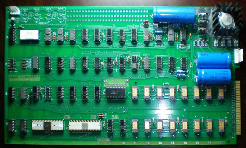
Cameron Cooper's Mimeo 1
Mistakes
in Apple's published schematics
These are a lot
closer to
reality than the Apple II schematics in the "Red Book", but there still
are a couple of errors.
In laying out the board and
reviewing my
net list with Apple's schematics, so far I've found the following
differences and errors between the schematics and the actual board.
- Address
line 7 is connected to pin 15 of the PROM at location A2
- Address
line 1 is connected to pin 6 of the PROM at location A2
- Some
inputs to the counters are left floating and not bussed together.
These are D6 pins 3&5, D7 pins 3,6,&11, D8
pin1 and D9
pin1
- Signal
VINH is described differently in the two places it appears, once as
/VINH (D8-7 & D9-7) and once as VINH (D15-13). It is
the same
signal.
- The 6800 section is connected
different from the actual board
- Connection
of capacitors C8 and C9 to digital circuit is switched with capacitors
C10 and C11.
- R16 and R18 are connected to gnd.
- R17
and R19 are connected to +5V.
- R22 and R23 is
connect to O1, not DBE
- R20 and R21 is connect to
DBE not O1
Less
than
optimal design practices discovered
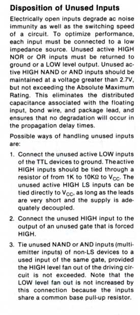
First
is the
floating inputs on D6-D9. To the right is a scan of
the
text from the 1982
Signetics TTL
Logic Data Manual. Signetics definately discouraged the
practice.
Note that one of the batches of Apple 1's that were built,
used a lot of Signetics chips.
Apple improved their practices as time went on as the Apple
II
rev 0, only has one floating input, and that probably was an inadvertant bug.
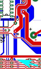
The
second less than optimal feature found was the design of the +12V bus
used to power the DRAMs. This bus comes down from the power
supply and reaches the area of the DRAMs on the bottom of the board.
There is a trace on the top of the board across the top of
each
row of DRAMs that carries the power to each chip. To go from
the
bottom of the board to the top, the designers used the +12v pin of DRAM
chips at location B15 and A15. Normally, separate feed
throughs
are used to move a power supply to different layers.
Once
again, this sort of feature is not seen in the Apple II rev 0.
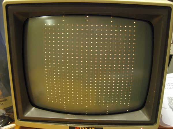
Video Imperfection
There
is a small flaw in the video section of the Apple 1, that causes spikes
in the video signal. This results in extra pixels in the display. Here
is a worst case display, with brightness turned way up, of those
pixels, with no characters displayed ( the screen should be blank).
I
have been able to confirm with some help that this fault also occurs on
the Obtronix and original Apple 1s(check out the "blank screen" show on this page). I’ve tracked this down to
cross talk between the video signal from C13-6 to the 3K resistor and
CLK03, which feeds the 2504s clocks. These two signals share adjacent
traces across the top of row D, just above the large ground trace.
Wendell
S. has done some further analysis and has determined that the fault is
caused by the high impedance nature of the video output circuit.
Wendell writes “The node driving the 3K can be very high
impedance when both C13-6 and D1-13 are high so the network is very
susceptible to pick-up as you described (nice catch!). The impedance of
the node is set by the base current of Q5 as it pulls down the emitter
followers in the TTL outputs.”
You can eliminate this flaw
by pulling down the output C-13, Pin 6 to ground, with a 2.2K resistor.
Another fix is to bypass the trace by lifting one leg of the 3K
resistor and C-13, pin 6 and running a jumper wire, avoiding the
crosstalk.
Critical Timing
The
74161 at location D-8 is subject some very tight timing. Tight
enough that 74161A parts will not work reliably in this location
because of slightly increased speed. The symptom of the problem
is that video gets out of whack while scrolling. Here is a
description of the problem
The high level of the input to D15-9
(preload) is just at 2 volts. There is a small glitch below 2 volts
just before the char rate clock(CLA) raises. D15 responds by lowering
VINH and things go south from there. D15 should preset VINH to high,
but apparently the floating preset input drops a bit at the same time,
resulting in a preset to zero. Apparently a 74161A at D8 is fast enough
to occasionally see VINH drop and counts on the nearby raising edge of
CLA, putting the state machine into a mess. Apparently the 74161
doesn’t have enough setup time to count at this point. The time
between early VINH drop and the next clock edge is about 20ns, but that
is just about at the limit of my old, uncalibrated scopes resolving
power, so consider this an estimate. This appears right on the edge of
the 74161 setup time spec. Apparently enough for an A part, but not
enough for a non-A part, which ignores this glitch and continues on
nicely.
I often wonder if this is the problem that Lisa Loop's Apple 1 was exhibiting back in the old days.
Apple 1, noise on -5 volt supply
I’ve
noticed long ago that there is a significant amount of noise on the -5
volt supply on the Apple 1. The -5 power supply is connected to 16 4096
DRAMs, 7 2504v shift registers, and the 2513 character generator, 24
chips in all, spread around the board. Beside a 22UF cap next to the
voltage regulator, there is only 1 .1UF decoupling cap connected to
this supply.
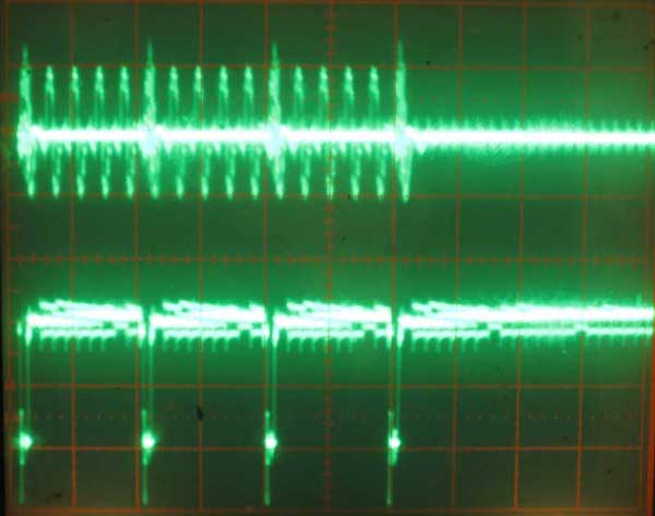
Apple 1 - minus five noise
Here
is an oscilloscope picture of this noise. Frequency of this trace is
set to 5 micro-seconds/division. Top trace is -5 taken directly from a
DRAM chip. Scale is .5 volts per division. Bottom trace is RAS taken
from same DRAM chip. Scale is 2 volts per division. You can see that
some of the noise on the -5 supply is being generated directly by RAS
switching. This working system exhibits over a .5 volts of noise on the
-5 supply to the DRAM chips.
While bringing up a new Mimeo 1
board, this excess noise on the -5 volt supply became a problem. This
board exhibited intermittent memory write failures, with writes of zero
bits occasionally failing. The bit would end up reading back as a one
sometime later in time. It took me quite a few hours of debugging to
figure out that the problem was due to all the noise on the -5 volt
supply. The fix turned out to be a simple replacement of the single .1
UF decoupling cap on the -5 supply with a different .1 UF cap.
For
those of you that don’t know, decoupling capacitors are typically
distributed around boards that have digital circuits to limit surges in
power demand from one chip from affecting the power supply to other
components. The capacitors act as small power sources that can supply
small amounts of power to nearby chips as the power demand from these
chip changes due to switching logic levels. A commonly used ratio of
decoupling caps to chips on a typical +5 volt TTL design is 1
decoupling cap to 2 74LSXX parts. I’m not sure what the ratio
should be for -5 volt supply in a MOS design, but the Apple 1
implementation is clearly insufficient and results in a lot of
switching noise on the -5 power supply.
Capacitors are rated for
deviation from the specified value. Typical variations for the ceramic
disc capacitors used in first batch Apple 1s are +80/-20. In order to
optimize putting a higher value capacitor in this location, I built a
simple capacitor tester. Future Mimeo kits will have a separately
packaged .1UF ceramic disc capacitor that tested as having a value
towards the higher end of the range seen. I recommend using this cap at
location B13, which is the -5 decoupling capacitor.
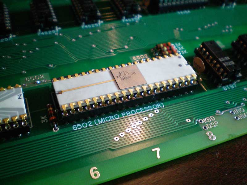
The 6800 Section
At
this time, I am not aware of anyApple 1 that was configured and run
with a 6800 processor. Steve Wozniak indicates that the 6800
section was actually designed for the 6800 pin compatible 6501,
so a 6800 monitor was never created. Steve does not remember
if they actually tested a 6800 on the board. Steve does
believe that they tested the clock circuitry, so the 6800 section
should work.
Note that MOS technology was sued by Motorola for producing
the 6800 pin compatible 6501. MOS technology withdrew the 6501 from the
marketplace, replacing it with the 6502. Only a few 6501's are
known to remain in existance.