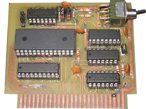
The First Homemade Prototype
My Apple II Firmware Board Project
See my Brain Board page for the latest incarnation of the firmware board.This board is a functional recreation of an original Apple II firmware board that uses inexpensive 27c128 or 27c256 EPROMs. 27128 or 27256 EPROMs should also work fine. Because of the denser EPROMs used, 6 sockets are replaced with one and the resulting size of the board is reduced to approximately 2 by 3 inches.
The board supports all functionality of the original Apple board
including:
- switch for enable/disable
- jumper for enabling ROM F8 - this was a solder pad jumper in the Apple design
- daisy chain enable functionality via DMA bus connections.
When in motherboard disable mode, and with a 27c256 PROM installed, you can even switch between the two banks of 27c256 PROM memory either with the switch or through software control, as if you had a ROM on the motherboard and an original Apple firmward card installed.
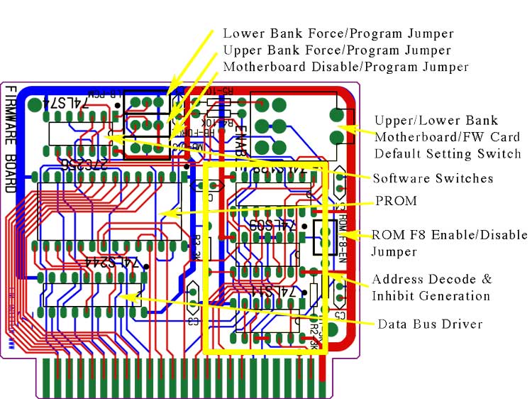
Here is a description of the 4 jumpers used to configure this board.
- Motherboard ROM enable/disable - completely shuts down the motherboard ROM during memory access to EPROM address space D000-FFFF or D000-F7FF if ROM F8 is disabled on the FW card. Uses apple's inhibit line for this purpose.
- ROM F8 enable/disable - disables or enables access to memory bank F800 on firmward card. If disabled, F8 ROM accesss are handled by the motherboard.
- High bank force/program - If configured to force - all accesses to firmware card 27c256 will address high half of this card. If set to program, high bank can be selected if force on low bank is not set. The on board flip-flop is set to select high bank either by the switch on power up or by software setting the switch. This flip-flop works the same way as the original switch on the firmware card, but can be used to select between high and low banks of a 27c256 when the motherboard ROM is disabled.
- Low bank force/program - If configured to force - all accesses to firmware card 27c256 will address low half of this card. If set to program, low bank can be selected if force on high bank is not set. The on board flip-flop is set to select low bank either by the switch on power up or by software setting the switch.
Here is a table showing the valid configurations of the 4 jumpers.
| Motherboard ROM disabled | Motherboard ROM enabled | ||||
| High Bank 27c256 Force | High Bank 27c256 Program | High Bank 27c256 Force | High Bank 27c256 Program | ||
| F8 enable | Low Bank 27c256 Force | invalid setting | Low FW board 27c256 bank uses low 27c246 F8 bank | invalid setting | switchable between motherboard and FW board low 27c256 bank switch or software selectible uses currently active F8 bank |
| Low Bank 27c256 Program | High FW board 27c256 bank uses high 27c246 F8 bank | switchable between low or high FW board 27c256 bank switch or software selectible uses currently active F8 bank | switchable between motherboard and FW board high 27c256 bank switch or software selectible uses currently active F8 bank | invalid setting | |
| F8 disable | Low Bank 27c256 Force | invalid setting | invalid setting | invalid setting | switchable between motherboard and FW board low 27c256 bank uses motherboard F8 ROM |
| Low Bank 27c256 Program | invalid setting | invalid setting | switchable between motherboard and FW board high 27c256 bank uses motherboard F8 ROM | invalid setting | |
A schematic with my modifications can be found here.
If you are interested in purchasing a kit or an assembled board, take a look at the Brain Board page.
Schematics for the original Apple Firmware board and a description of operation can be found in the book "Understanding the Apple II", which is available online in a couple of places. When using 27c128 PROMS, the jumper settings must be set so as to force the address to select high bank.27c128 or 27c256 parts are programmable using inexpensive Willem prom programmers that are very inexpensive on EBAY. I bought my programmer on EBAY for only $19.00 on ebay. Parts come with or without windows which make them erasable or not. I bought several without windows since they are very inexpensive (around $1.00 each) and I didn't want to bother with finding or building an EPROM eraser.
Other than the enhancements listed above, the design is pretty much the same as the Apple Firmware board design. I tried to find a way to reduce chip count, but couldn't find a way to do it, without resorting to programmable logic. The major difference is that the individual chip selects coming out of the 74LS138 are not used. Instead the 74LS244 enable coming from the 75LS11 is also used to select the EPROM. Additional address lines are routed to the EPROM in order to support the extra address space in these parts. These address lines were already connected to the 74LS138. The output of the 74LS74 flip-flop which enables the Firmward card via the 74LS138 is also used to enable the EPROM.One thing to note is the gaps in addressability when using the 27c128 or 27c256 EPROMs on this board which can only addresss 12K of memory. Use the table below in order to program the EPROMs correctly.
| Apple ROM Address Space | 27c128 or 27128 Address (high bank selected) |
27256 or 27c256 Address (high bank selected) |
27256 or 27c256 Address (low bank selected) |
| not addressable | 0000-0FFF | 4000-4FFF | 0000-0FFF |
| D000-D7FF | 1000-17FF | 5000-57FF | 1000-17FF |
| D800-DFFF | 1800-1FFF | 5800-5FFF | 1800-1FFF |
| E000-E7FF | 2000-27FF | 6000-67FF | 2000-27FF |
| E800-EFFF | 2800-2FFF | 6800-6FFF | 2800-2FFF |
| F000-E7FF | 3000-37FF | 7000-77FF | 3000-37FF |
| F800-FFFF | 3800-3FFF | 7800-7FFF | 3800-3FFF |
The layout has chips flipped upside down verses typical Apple II expansion cards in order to simplify layout. It turns out that I was able to layout this board with only a few vias.
Here is the parts list, with Mouser
parts numbers for many of the
parts. Total cost (minus the PCB) should be less than $20.00.
| PART | QUANITTY | MOUSER PART NUMBER |
| 74LS09 | 1 | 595-SN74LS09N |
| 74LS11 | 1 | 595-SN74LS11N |
| 74LS74 | 1 | 595-SN74LS74AN |
| 74LS138 | 1 | 595-SN74LS138N |
| 74LS244 | 1 | 595-SN74LS244N |
| 27C256 | 1 | 511-M27C256B-90B6 (OTP - cost around $1.00) |
| jumper | 4 | 538-15-29-1025 |
| right angle switch | 1 | 633-M2022S2A2W30-RO (most expensive item - around $6.00) |
| molex KK | 1 | 538-22-10-2021 |
| 3K resistor | 4 | CF1/4CT52R302J |
| 10K resistor | 2 | CF1/4CT52R103J |
| .1uF +80%/-20% capacitor | 5 | |
| 16 pin socket | 1 | |
| 14 pin socket | 3 | |
| 28 pin socket | 1 | |
| 20 pin socket | 1 |
Here is a view of both layers (red is top, blue is bottom) of the layout with silkscreen (black).
Back to Mike's Hobby Home Page