
Apple II Repair Tips
Note that authorized Apple dealers repaired boards by swapping them out for tested
and repaired boards provided by Apple. They left the board level
debugging to Apple.
"Shotgun" Repairs
These approaches may restore many boards to operational status, but certain faults like opens, shorts in the PC board or bad sockets will not be found.
Bad Connections: reseating the chips
Basically most Apple II's and Apple IIplus machines that don't work correctly, can be "repaired" by reseating chips that aren't making good connections with their sockets. This is the number one problem that occurs with early Apple II's and Apple II plus machines. Finding the chip with the bad connection can be a challenge, but if you are desperate, you can always reseat every chip on the board.
Bad Chips: Exchanging the chips
If reseating the chips doesn't
work, then you might have a bad chip. One way to
trouble shoot this is to swap one chip of the same type for another of the same
type and see if behavior of the system changes.
You can also swap chips with chips from another known "good" board.
Except for the ROMs, almost all of the
chips on the Apple II are still manufactured and available from distributors
like mouser or digikey. Some parts are even
available from Radio Shack.
Targeted Repairs
The best way to repair a board is to understand the circuit and use an oscilloscope to debug it. This will save wear and tear on old chips and sockets and allow you to fix problems not found by simple swapping/reseating of chips.
What you need
You need an oscilloscope and schematics in order to
pinpoint problems without swapping chips. The famous "Red Book" has
the required schematics as well as a nice system diagram. The schematics
and detailed circuit descriptions can also be found in the book "Understanding
Your Apple II" by by Jim Sather. This book is available for download
in pdf format from http://alfter.us/files/uaii.pdf. Older Tektronics oscilloscopes can now be had for very low prices
on Ebay or you can buy a new USB scope that uses a PC
for monitor and control for a few hundred bucks. Keep in mind that
bandwidth may become important as there are some fairly high frequencies in the
video circuit. For instance, a 60 MHZ HP digital storage scope that I
once borrowed didn't have the bandwidth to troubleshoot a color video problem.
It didn’t have enough resolution to detect the master crystal was
out of tolerance. I finally only changed
it only after examining the rest of the circuit and finding no fault.
There are two common errors for Apple II's that are
not working: no video and/or system will not boot.
System will not boot
A common failure for a non-working Apple II is that it will not display prompt or boot. You will not even hear the bell, which is done almost immediately after reset is removed from the processor. This is because a large portion of the logic of the Apple II needs to be working before the computer can even get this far. The following parts of the system are required to work in order to ring the bell and get a prompt. In parenthesis is the schematic page in the "Red Book". Be aware that all portions of all of these systems don’t have to be working perfectly in order to get a boot, but some components of each of these systems are critical.
- Power supply
- Clock and timing (S-3)
- Processor (S-2)
- Address bus (S-2, S-5, S-6, S-7, S-8, S-9, S-10)
- Data bus (S-2, S-5, S-8, S-9, S-10)
- Latched data bus (S-8, S-10) data from onboard I/O or DRAM is read back to processor with this bus
- PROM (S-5)
- Ram address mux (S-7) used to share memory between processor and video
- Dynamic RAM (S-8)
- On-Board I/O (S-10) latches data from DRAM for reads from processor
The parts of the system that are not required in order to get a prompt (beware that without video, it is hard to tell how far it gets past the startup beep).
- Video Sync Counter
- Video Generator
- Peripheral I/O - (expansion slots)
For debugging I would recommend following this sort of sequence
- Check voltages from power supply
- Check processor to make sure it is not being held in reset
- Check processor to make sure it is receiving 1MHZ clock
- Check address bus to make sure that all signals look normal
- Check data bus to make sure that all signals look normal
- Check chips selects on ROMs to see which ones are being selected, if any.
- Check R/W line to see if processor is just reading instructions or writing data, as well
If everything looks normal, then you must try to find out what is happening right after boot. You want to reset the system and check the signals as she boots. Check to see that the F8 ROM is selected right after reset and the output from the ROM looks reasonable both on the ROM itself and back at the processor. DRAM is also accessed just a few cycles after boot when the processor calls a subroutine and the return address is put on the stack. Almost immediately, the screen is put into text mode and the bell is rung.
No Video
If your system beeps and boots from floppy disk, but doesn't display video, you problems are far more constrained than a system that simply will not boot. This problem is probably limited to one of the following.
- Clock frequency (timing could be slightly off or you could have wrong crystal)
- Video Sync Counter (S-4)
- Video Generator (S-11)
The DRAM address mux (S-7) is used to refresh memory and share DRAM between processor and video. Note that the video system was designed to work at either PAL or NTSC frequencies. Some cuts and jumpers are made on the motherboard to switch frequencies. The master crystal is also changed out to a slightly different frequency for PAL operation. I once spent a considerable amount of time trying to figure out why the vertical sync wouldn’t lock on a new board I had just obtained from eBay. It turned out that it was set up for PAL. Reconfiguring the board to NTSC timing and changing out the PAL frequency crystal to an NTSC frequency crystal solved the issue.
Apple Service Notes!
Check out these service notes
that someone sent me. There are a lot of tips in this doc,
including information on peripheral cards. I found at least one
error while putting these notes into PDF format, so beware, but there are a lot of good ideas in there.Testing Ram
Apple's programmers aid prom contantains a nice memory test that can be run from PROM. I have ported a 6502 memory test to the Apple 1 and Apple 2, but it runs from memory, so the system has to be pretty functional for it to work.Example Debugging Sessions
Case 1:
Typical
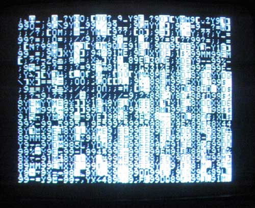
No Prompt Screen after
One system that would not boot, was recently debugged.
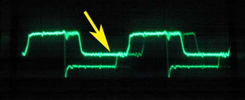
Data Bus But Not Driven Completely to
All expansion cards were removed. After probing the clock, data and
address pins on the processor with an oscilloscope, I found that the data bus
had some bits that looked odd. These bits were not being driven
completely down, but only down to 2.5 volts during some cycles.
The R/W line was never being driven low, so I knew that the processor was
trying to read, and was never writing. After studying the schematics, I
found that there were two primary sources for data on the data bus for reads
when no I/O cards were present. One were the ROMs
and the other was the latches on page S-10.
These latches are 74LS257s at location B6 and B7 on the motherboard. I
checked the ROMs to see which ones, if any, were being selected and found that
only ROM F8 was being read. I pulled the 74LS257s and the data bus looked
cleaner, though I knew the system couldn't boot, since it couldn't read DRAM
without these latches. Next I removed the case from the Apple II so I
could reach this section of the mother board with an oscilloscope probe. I also put the 74LS257 chips back in place.
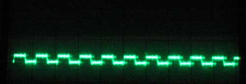
Bad Select - F2, pin 12 (less than 1 volt in high state)
I looked at the enable line to the 74LS257s and found it looked funny, being
partly driven with a signal of less than 1 volt. As expected, the latches
were being selected at the same time as the
Total time to diagnose this problem was about an hour and a half.
Case 2:
After debugging the problem described in case 1, I found that I could now get both a monitor and a basic prompt. However the system would still not boot from floppy. The disk would make noises, but wouldn’t load DOS and start up.
First part of the debugging session involved eliminating the disk controller, floppy and drives from consideration as the source of the fault. This was done by swapping out each of these items with spares that I had available. The result in each case was the same failure to boot. The next step was to move the controller to a different slot in case something was wrong with the slot or slot select logic. No change in symptoms occurred. This pretty much eliminated the floppy sub system or the slots themselves as being at fault. At this point, I called it a day and turned on the TV to see what the Boston Bruins were up to. I did take the schematics along to look for possible fault areas. It turned out to be a good idea as the Bruins soon found themselves on the losing side of a 4-1 score.
The next morning, I had some new energy. Since the system did give me a monitor and
basis prompt, I felt the culprit was most likely the memory subsystem
addressing logic. In order to diagnose
this, I wrote a simple address in address ram test in Applesoft
basic for the memory subsystem. The problem
was most likely in high order bits (8-15) of the address. I didn’t think you would get a monitor
or basic prompt if the system had a problem with the low order bits (0-7) of
the memory addressing system. This program
pokes the high order byte of each location’s address into each memory location
from 6000 to 49151 with a for loop. It then checks the contents of each location to make sure that it was written correctly. The starting point of
6000 was pretty arbitrary, but was high enough to avoid having the program
write over itself or it’s variables.
This is what I should have written. For a memory test, always write
all of memory, before checking it. The hardware error would have caused
the program to write over itself and crash before finding the error. However
it would have been obvious that there was an issue, because video memory
would have been written over, prior to the crash.
10 PRINT “WRITING MEMORY”
20 FOR I = 6000 TO 49151
30 I%= I
40 J%=I/256
50 POKE I%,J%
60 NEXT I
70 PRINT “CHECKING MEMORY”
80 FOR I = 6000 to 49151
90 I%=I
100 J%=I/256
110 IF PEEK (I%) = J% THEN GOTO 140
120 PRINT “ERROR AT ADD:”;I%;” DATA:”;PEEK(I%);” EXPECTED:”;J%
130 GOTO 160
140 NEXT I
150 PRINT “NO ERROR”
160 END
This is what I actually wrote. Turns out the print statement
moved video memory prior to the read, causing the peek to fail since it was
reading video memory instead of the correct address space. What really
made me realize that there was an issue with addressing was the data being
written to video memory showing up on the screen.
10 FOR I = 6000 TO 49151
20 I%= I
30 J%=I/256
40 POKE I%,J%
50 PRINT I%,J%
60 IF PEEK (I%) <> J% THEN STOP
70 NEXT I
80 END
The results of running this program was an immediate failure
at location 6000, revealing that something was wrong with memory
addressing. I also noticed that characters
filled the screen when this program was run, which was very strange, since low
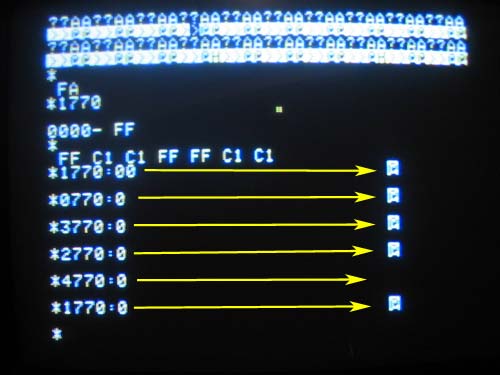
res display memory starts at address 1024 and only runs for 1024 bytes. In order to diagnose further, I dropped down
to the Apple’s monitor and converted the address 6000 to hexadecimal 1770. Poking variations of the hexadecimal address
1770 revealed that 770, 1770, 2770 and 3770 all affected the same memory
location. This was a bit easier to track
down than it sounds, since 770 is a visible part of screen memory and writing zero
to any of these locations immediately showed up on the display as an inverse
video character. This indicated that
bits 12 and 13 of the memory address were being somehow tied together. It was now time to get out the oscilloscope.
To make signals easier to see on the scope, I wrote a simple assembly language program to continuously read from location 1770. This machine happened to be an original Apple II with the mini assembler in ROM and I used it to write the program, but it wouldn’t be much harder to manually enter the 6 bytes necessary for this program using the monitor. The program was.
8000: LDA $1770 ;AD 70 17
JMP $8000 ;4C 00 80
I started the program by typing the monitor command 8000G. Using the oscilloscope, I looked at the address bits on the processor pins 22 and 23. They looked good with address bit 12 toggling high, every cycle in which location 1770 was read and bit 13 staying low all the time. Then the address bus drivers at H4 and H5 were examined at pin 3 on each. Everything looked normal here, as well. The address bus must be ok, if the output of the drivers looks good. The only place remaining where there could be problems with the addressing of DRAM on address lines A12 and A13 was detailed on page S6 of the schematics. I started examining A12 and A13 related signals on chips described on this page of the schematics. As expected, I found that bits A12 and A13 of the address bus looked OK. However the output pin 7 of the 74LS153 multiplexer at C1 that uses A12 and A13 as inputs wasn’t being driven properly. The output from this pin was less than a volt, similar to the output of the 74LS139 in the previous case. I pulled out the jumper block that this signal was connected to, in order to make sure that some other fault wasn’t disturbing this signal. Pulling the jumper block did not affect the signal. I now assumed that this chip was bad and I swapped this chip with a good 74LS153. The output now looked good and the system was able to boot.
Total time to debug was about 2 hours spread over two sessions. The first session was mostly spent eliminating the floppy disk subsystem. The majority of the real progress was made in the second session. I started the second session by focusing in on the addressing of the memory subsytem. Once the memory addressing test was tried and failed, it didn’t take long to track down the root cause of this problem.
I’m still concerned about why two chips in the same section of this computer’s logic failed in a similar way at the same time. With the chips replaced, examination by a scope reveals nothing unusual. I’ll have to keep a close eye on this computer for further failures.
Case 3:
I had a spare board of the same rev level and I started swapping chips. Mostly, I tried chips that were connected to various chip selects such as address decoders. Not much luck with that. I did write a simple address in address test and got it to run, when the machine was being somewhat nice to me, but it found no problem. I decided to drag out the old copy of Red Book schematics, and take a break. Thinking that addressing was probably OK, I thought about what other kind of problem would give me this kind of flakey results. The next obvious choice was the data bus. I swapped the 8T28s data bus transceivers, but got the same results. I swapped memory from one bank to another in case a memory chip was going bad on me. No change. Looking at the schematics again, revealed a couple 74LS174's buffering the DRAM data outputs(B5 and B8). I swapped these with the chips from my donor board and the problem went away. I swapped them back and the problem returned, showing that the problem wasn't a bad connection in the socket. I now swapped just one of the two chips and found the problem disappeared, once again. Total time to resolve the issue was about an hour and a half.
Moral of this exercise is that random chip swapping will probably not get you to a solution very rapidly, at least without some thought. The chip swapping approach needs to be done with some strategy in mind. When I was first just swapping likely chips in the addressing area, I really wasn't using my full knowledge of the computer. Once I pulled out the schematics and really thought about it, I found the problem rather quickly.
Also See My VCF Presentations
Back to Mike's Hobby Home Page