PS/2 keyboard adapter calibration notes.

I put the design files for my PS/2 to parallel ASCII adapter online when I ran out of PCBs. I get an occassional question about programming the AVRs. Mostly it is straight forward, however for the RS232 port to work properly, the internal RC-oscillator must be calibrated. Here are some notes about the calibration procedure.

Calibrating and programing is a four stage process. The calib and operation FW are built from the same source. Look in the source for a .IFDEF CALIB to see the difference.

When booting the calib image, it will output a 4Khz square wave out port B.

The calibration is done by connecting a terminal to the serial port and typing one of the following 4 commands.

I – this increases the calibration frequency
D – this decreases the calibration frequency
W – this neither increases or decreases frequency
Q – this quits the calibration process, displays the calibration variable, writes it to the last location of EEPROM and exits the calibration process

You need to connect a frequency counter or scope to one of the “B” port outputs and either increase or decrease the frequency until it is as close as possible to 4Khz. These days, many inexpensive meters have frequency counters that will be accurate enough for this job.

The AVR will not echo the correct character to the RS232 port, when it is out of calibration. The calibration routine will default to decrementing the calibration value if it receives a character that it doesn’t understand. Just keep typing and eventually it will wrap around into a good range, at which point you can fine tune it.

So the four steps are:
1) First load the calib file (AVRPS2_keyboard_calib.hex) and run it to adjust the frequency, as described above. When you have the frequency in a good spot, type Q and the the controller will output the calibration value and also writes it to the last location of the EEprom. For record keeping purposes, it is a good idea to write the calibration value with a marker on the underside of the chip when you are done.
2) I have an AVR dude script that reads the EEPROM – I would run this to get the calibration value into a hex file.
3) Now you can program the regular firmware (PS-2keyboardv3.0.hex). Unfortunately, with AVRdude, this process also erases EEPROM, so you need to reprogram the calibration value into the last byte of the EEPROM.
4) Reprogram the calibration value into EEPROM using the AVRdude script provided, using the EEPROM file you read from the system in step 2 and you are done.

If you are doing a batch of them, once you get things set up, it takes only about 30 seconds or so to go through the scripts, to calibrate and program, each part.

In this design, it would have been nice to use a crystal for clock generation to avoid the calibration hassle. However, that would take two pins of the AVR, which I didn’t have available. I could have freed up a couple of pins by configuring the settings with the keyboard or serial port. It would have taken time to write the software that I didn’t have available, as, at that point, I was in the middle of the inital Apple 1 cloning effort for Mimeo.

First Pass of a Mantua General Repaint

First see this old old blog post about the remotoring and change to the drawbar that I did a few years ago.

I am not a master modeler, but more recently, I’ve been working on changing an old Mantua General Locomotive over to the paint scheme of a US Military Railroad Norris type locomotive. With City Point being my main area of focus, I found some really good images of the Govener Nye, and decided to use that locomotive as my prototype.

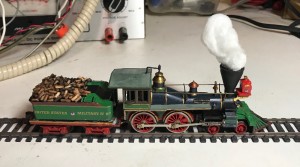
The original paint job was severely chipped and probably not very great to start with. I stripped the old paint off with lacquer thinner and then repainted. Here is the result.

Generic USMRR Locomotive - paint based on Govenor Nye, a Norris built 4-4-0

Generic USMRR Locomotive – paint based on Govenor Nye, a Norris built 4-4-0

I used an ancient can of Humrol #96 RAF blue that was left over from my days as a wargamer for the Russian iron, and am very pleased with the result. Other paints were from what I had on hand. I’m not all that happy with the green, but it will do for now. Decals are from Microscale’s Eastern USMRR set.

Besides the repaint here are some other things that I have done with this locomotive.

I added a DCC decoder using a Digitrax DZ-123 Z scale decoder, which can handle the 1 AMP motor. At this time, I don’t plan on adding sound to my Civil War locomotives, thinking that an external sound system will be more impressive. For example, I’m contemplating having an actual whistle that will be controlled with the DCC throttle, just like any other locomotive with a built in sound system.

I also added an engineer to the cab, but he is not very visable.

After mucking around for a bit trying to make the Matua supplied wood pile look more realistic, I ended up replacing the wood in the tender. I scored the sides of some round toothpicks with a fine tooth metal cutting sabre saw blade. Then I stained them and then cut them to size using a end cutting pliers. After positioning them losely on the tender, I used diluted elmers glue to attach them to the top of the tender.

What’s up next? I will add a line so the miniature engineer can ring the bell. I’m considering adding a working headlamp, but that may wait for a later date. I also need to program the speed tables for the DCC decoder. I will probably add a small magnet to the smoke/steam, so it can be removed when the locomotive is shut down, yet be a little more firmly attached when the locomotive is in motion.

IMac repair

I have a 5 year old IMac that recently started to act up in a most annoying fashion. Every couple of hours it would shut itself off, with absolutely no warning.

Right from the first occurrence, this felt like a power supply issue. I could power it back up, simply by unplugging the unit, waiting a few minutes, and turning it back on.

Research on the internet, revealed that others had similar issues, and also how to get inside the unit. One symptom of this failure is that the sys log showed the last restart was done to loss of power, not some kind of crash.

Knowing how expensive Apple service would likely be, I decided to look into fixing it myself. I carefully worked a putty knife between the display and the chassis to get it open. What a horrible design, it’s so bad that it’s hard to comprehend that Apple would ship something like that. I managed to crack one corner of the glass getting it open, but it wasn’t a fatal crack, and the display remains perfectly usable.

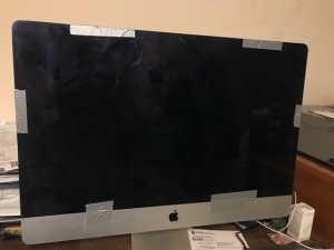
Anyway, I removed and examined the power supply, looking for the telltale signs of a damaged component, but couldn’t find anything obviously wrong. I decided to reassemble the unit, hoping that perhaps one of the connectors was intermittent. I decided to use duct tape to reattach the screen, in case I might need to attempt something different, like replacing the power supply, altogether, in order to get the system fixed.

IMac held together with duct tape

IMac held together with duct tape

After powering up and running for a few days, the problem returned, so I knew it wasn’t a faulty connector. I decided to take one more look at the power supply before ordering a replacement. This time, I repeated the scan for obviously fried components, but found none. I did notice that the soldering on a few of the through hole components, just didn’t look that good. The solder job looked like the heat wasn’t enough to draw the solder down into the holes, so the solder was kind of balled up on the legs of these parts. Getting the heat right on a board like this, probably isn’t easy, as it contains a mix of small surface mount parts and through hole parts, that are connected to relatively large heat sinks.

I decided to reflow the solder on the suspect components and see if the system would work more reliably. I went ahead and took a shot at it and put the system back together (with duct tape). I’m still not sure if I fixed it, but three weeks later, I haven’t seen a reoccurrence of the random power off. However, it wouldn’t surprise me at all if putting up this post doesn’t cause an immediate reoccurance of the issue!

Operating an Original SCELBI 8B

I recently spent a few hours with Mark Arnold and his original SCELBI 8B. This is the very machine that Mark used to develop SCELBAL with, way back, in 1975. Towards the end of our debug session, we had the machine in a largely working order!

Mark Arnold with his SCELBI-8B

Mark Arnold with his SCELBI-8B

We spent a lot of time, troubleshooting what appeared to be an intermittent EPROM issue. Finally we discovered that that the edge connector on the EPROM board wasn’t making reliable contact with the connector. After examining the board in detail, we noticed tarnish on the edge connector contacts. We used a soft pencil eraser to clean the tarnish off of the contacts and the intermittent operation completely disappeared. Fixing a computer with a pencil eraser was a first for me, though I expect others have done the same. Once the repair was done, Mark was able to reliably run a variety of MEA operations without any problems.

With only 4K of SRAM installed, we were unable to load the full floating point SCELBAL, but we were able to load tiny SCELBAL using a simple bit-banged RS232 port. Once loaded, Mark successfully entered and ran some small BASIC programs. Weeks later, I understand that Mark still has the system powered on and it responds to MEA commands, without any need to reset or reboot.

In order to declare that the machine is in 100% working order, a few things still need to be checked out. We had only 4K of SRAM installed, the other 8K should be added back into the system. We used a modified version of MEA with the page 76 EPROM changed. I created a version of page 76 EPROM with a 2400 baud driver, but we were having some issue with corrupted serial output characters. We don’t know if that was a ground loop problem or a baud rate problem with the modified page 76 driver. Serial input at 2400 is working perfectly, but the timing for output is done differently, so it could be either.

Finally, the cassette interface needs to be connected and tried out. I don’t really expect any issues with that, as I have used that particular cassette interface with a reproduction SCELBI 8B, back when I was first troubleshooting my reproduction cassette interface.

Repairing an Old Automobile Tape Deck

Quite of a bit of the stuff I own and use everyday is, let’s just say old. This includes a 1988 Mustang convertible that sometimes becomes my daily driver. This car is what they call “bone stock”, and I like to keep it that way, though there can be challenges with it. One of the challenges is the sound system that gives you the option of a FM/AM radio or cassette tapes. Lately I’ve been relying mostly on the cassette tape player.

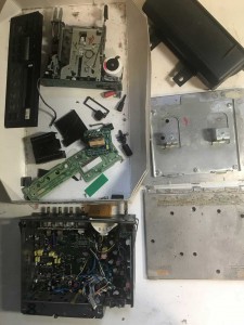
The problem with the cassette tape player is that after so many years, the pinch roller losses it’s grip, and the tape plays at too high a speed, giving you awful Donald Duck sounds. The last time that happened, I found an exact replacement tape deck on eBay and simply swapped it in. Well, eventually the replacement deck started exhibiting the same issue. This time around, though those decks can still be found on eBay, I figured that I would try to fix it. This became a multi-week adventure, as I stripped down both decks, swapping the best components of the replacement deck onto the original deck, which I had kept stashed in the attic. In the end, I ended up with a pile of parts and a working deck, but it wasn’t easy.

Radio in Pieces

Radio in Pieces

Here is some of the stuff that I did to get a working tape deck.

  • The original deck had chipped corners on the front bezel, so I swapped in the bezel from the replacement deck. In doing this swap, some of the wires on the flat flex cable connecting the front PCB to the main PCB were damaged, so jumper wires had to be added to repair this.
  • The backlight for the original deck’s display was gone, so I had to swap in the backlight from the replacement deck. This might actually be the light that was originally in that deck.
  • A power supply trace on the main PCB was found to be broken and had to be jumpered over.
  • I’m not sure, but I think the original tape deck had an issue with a switch, resulting in the tape playing at fast forward speed, similar to the slipping pinch roller sound. Rather than troubleshoot, I ended up swapping in the replacement deck, after cleaning the pinch rollers, which is was next step.
  • The pinch rollers on the replacement deck were cleaned, as best I could. In fact, if I had done this in the first place, that is all that I would have had to do.
  • Reproduction SCELBI 8B demonstrated at the Museum Of Computing History (UK)

    I just received this report from David Williams in the UK.

    Hi Mike,

    Just thought I’d drop you an email to let you know, I took my SCELBI 8B to the Retro Computer Festival at the Museum Of Computing History last weekend. Only a handful of people recognised the system initially but hopefully a few more people are now aware of the history behind the machine.

    I spent a good while describing the system to one chap who I later discovered is the guy heading up the EDSAC replica build at Bletchly Park.

    I was able to demonstrate the basics of the system using the monitor program to edit & display memory along with entering short programs. I couldn’t get SCELBAL to load due to a RAM fault (Only Identified when I got back home) which was a shame.

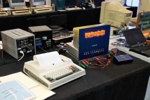
    I’ve attached a photo of the setup. Terminal being used is a TI Silent 745. The box below the SCELBI is the power supply, Teletype interface to the right and a fast-load box as described in issue 1 & 2 of the SCELBI newsletters.

    Cheers,
    Dave

    David William's 8B (reproduction)

    David William’s 8B (reproduction)

    SCELBI 8H Usability Reasessment

    For a long time, I would say that the SCELBI 8H was the first practical computer marketed to the general public. The key word being practical, as certainly many of the other personal computers of the day, were not very useful machines, other than for educational purposes, at least without adding additional capabilities to them.

    From the time that I got my reproduction SCELBI 8H working, I’ve been able to demonstrate a number of interesting, practical applications on it. That I was able to do so, was justification for the claim that a SCELBI 8H was a “practical” computer. However, I’ve always used a second computer to assemble the source code and then downloaded the application to the SCELBI through a serial port. A few months ago, when I talked to Bob Findley, I asked about how they did application development for the SCELBI 8H. It turns out that Bob and Nat used almost exactly the same approach that I used. Only thing is that they used a PDP-8 as a platform for the cross assembler and a teletype with it’s paper tape punch/reader to download the program to the SCELBI. Though the cross development platforms are different, what Bob and Nat did, was essentially the same as what I’ve done.

    I’ve come to realize that though you can run some interesting, practical applications on the SCELBI 8H, it really can’t do it, without either help from a host computer, an impractical amount of time, or the addition of features like a built in monitor. After talking to Bob, and thinking about it a bit, I guess I’m ready to say that though the SCELBI 8H, as shipped, can run practical applications, it was not a very practical stand alone computer. However, that still doesn’t remove the significance of the SCELBI 8H as the first offering from one of the very first personal computer startup type companies.

    Note that the limited capabilities of the 8H were recognized by Nat and Bob, who developed the follow on SCELBI 8B, with it’s extensive built in software suite. More about the 8B in a follow on post.

    How Many SCELBI’s Were Really Sold?

    According to Bob Findley, whom I spoke to earlier this year, the often quoted number of 200, is an exageration. Bob said they sold more than 40 completed systems and over 100 board sets.

    One interesting thing that Bob said, is that until the Altair came to market, they felt that they had the market to themselves. The Mark-8 wasn’t considered a competitor, as it wasn’t sold as a functional system.

    I also found out why there are so few Oscilloscope interfaces remaining (only one is known to exist at the CHM). Bob said that they only sold about 4 of them.

    More information from Bob in a follow up post.

    ENIAC in Action Book Review

    First of all, let me tell you that I’ve had a hard time writing this review, as I enjoyed reading the book quite a bit, but I think that the book is not for everyone. I really wanted to write that everyone should read this book, as the reader will learn a lot about what happens in new product development, which is more relevant these days, than ever.

    Anyway here goes the rest of my attempt of a review.

    Eniac in Action by Thomas Haigh, Mark Priestley and Crispin Rope is a different kind of book in some ways. First off, it goes into a significant amount of technical detail. Much of this detail would be hard for a “lay” reader to understand. This is the part that I think may cause problems with some readers. Technical detail aside, where the book really shines is how it describes in detail, the process that it took to create, maintain and eventually enhance ENIAC, a fairly complex implementation of a new technology.

    The development of ENIAC was filled with many challenges and obstacles, which the authors describe in a very engaging style. The details of ENIAC development are unique. However, in my opinion, when compared to the process of developmenting other complex systems, there isn’t much that is really different about the ENIAC. That is why I think everyone should read this book. You will get an understanding of just how hard it is to “change the world” with revolutionary new products and systems. Development of complex, new systems are always problematic and take time to sort out. Certain people in the process will get most of the credit and many, many people will be forgotten.

    Reading ENIAC in Action will give you a glimpse of one such project. When reading it, keep in mind that there are many engineering teams around the world currently engaged in similiarly daunting tasks.

    Early Draft SCELBI HW Construction Manual Available

    This is a very early draft. Consider it to be full of errors, so compare to original documents that can be found at scelbi.com, before using. The main reason I’m posting this, is that I have created and added a couple of chapters for assembly of the oscilloscope interface. Any original documentation that existed about the oscilloscope interface has been lost. I still need to create a chapter with technical information on the oscilloscope interface, including a bill of materials, schematics and theory of operation, but this is a good start. I also need to add a section on PCB rework for this interface. The other chapters will also get revised, as I find time, with photographs of the boards and any notes or errata that I have discovered.

    http://www.willegal.net/scelbi/8BHhardwarebook.pdf