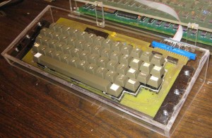
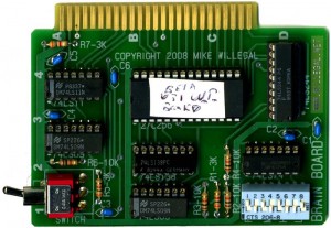
For people that still had the FCS, 4.0 PROMs, version 5.1 PROMs were shipped on Monday and should be in your mailboxes soon. I will only be updating version 5.0 PROMs upon request. The only difference between version 5.1 PROMs and 5.0 PROMs, is in the power up screen and it doesn’t affect operation in any way.
Though assembly is really straight forward, there is one thing to watch out for when assembling Brain Boards. Where the traces run between pads, the soldermask reveal extends right up to the edges of the traces and, on some boards, where registration isn’t perfect, the solder mask reveal may expose a tiny part of the trace. There is potential here for shorting the trace to the pad when soldering a component to this pad.
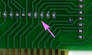
Brainboard-soldermask
When soldering these pads, be careful that you don’t accidentally bridge the gap between the pads and the adjacent trace. If you can’t get rid of the bridge with a solder wick or solder sucker, the easy fix is to cut the solder bridge with a hobby knife. Check continuity with an ohm meter to make sure the connection is broken.
Is the Brain Board Designed Upside Down?
It’s funny that no one has questioned or commented about the upside down layout on the brain board. This was done on purpose because of the vastly improved layout possible with upside down chips. The layout of the address and data bus connections between the 27c256 and 74LS244 sockets and the edge connector would be much more complicated if the chips were right side up. Flipping the 27c256 right side up moves the data bus connections of the 27c256 to the opposite side of the chip from the 74LS244 and Apple data bus. Also, all the lower address lines would have to be crossed to properly connect the 27C256 to the Apple bus.
Once I flipped the 27C256, I figured I had to flip all the chips and the silk screen to prevent confusion and mistakes during assembly.

