This morning I soldered the sockets, resistors, capacitors, and 555 timers (they are not mounted in sockets) onto the Datanetics PCB. There is a dot etched in copper near pin 1 of the DIP sockets. I used the schematics on my Datanetics page as a reference, so I put the seven resistors and three caps into the correct locations.

Components soldered in
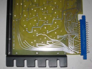
While I had the soldering iron out, I also made two cuts on one of the shorted traces that makes an x towards the bottom of the front of the board and jumpered it over the other trace. This was a layout error on the original that I faithfully replicated.
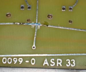
cut and jumper
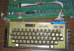
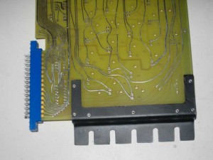
Before adding the MM5740 and 7404s, I wanted to check to see if the 555 timers were generating good clocks. in order to do this I needed power. Rather than mess with jumpers, I figured I might as well as wire the DIP – ribbon cable – Edge connector. This picture was taken later on, but shows how it is wired. The red aligator clip is a ground probe connected to my oscilloscope. Once I confirm that everything is working, I’ll apply some heat to the heat shrink tubing to lock it in place.
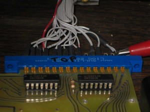
Edge connector
Connections from the A1 keyboard DIP socket to the edge connector are as follows.
EDGE CONNECTOR TOP (12 positions connected)
starting on left side
-12V – CONNECTOR PIN 1 to DIP PIN 11
B6 – CONNECTOR PIN 2 to DIP PIN 7
B5 – CONNECTOR PIN 3 to DIP PIN 6
B4 – CONNECTOR PIN 4 to DIP PIN 2
B1 – CONNECTOR PIN 5 to DIP PIN 5
B2 – CONNECTOR PIN 6 to DIP PIN 4
B3 – CONNECTOR PIN 7 to DIP PIN 3
RST1 (RST) – CONNECTOR PIN 8 to DIP PIN 1
RST2 (RST-GND) – CONNECTOR PIN 9 to CONNECTOR PIN 15 (GND)
STROBE – CONNECTOR PIN 11 to DIP PIN 14
B7 – CONNECTOR PIN 12 to DIP PIN 8
GND – CONNECTOR PIN 15 to CONNECTOR PIN 9 to DIP PIN 9
EDGE CONNECTOR BOTTOM (3 positions connected)
Counting from same side as we started with on top
+5V – CONNECTOR BACK PIN 4 to CONNECTOR BACK PIN 9 to DIP PIN 15 to DIP PIN 16
CLEAR SCREEN – CONNECTOR BACK PIN 8 to DIP PIN 12
CLEAR SCREEN (+5V) – CONNECTOR BACK PIN 9 to CONNECTOR BACK PIN 4 (+5V)
Next I connected the keyboard to a Mimeo and powered up in order to check the clocks. Like always during a first power up, I first checked for hot chips and for good voltages on the power supply. Then I checked repeat and MM5740 clock with an oscilloscope. Everything looked just fine. By shorting the pads together at the location of the reset key, I was able to verify that reset was connected correctly. By doing the same, I was also able to verify that clear screen worked. Next step was to plug in the chips and see if I could enter characters.
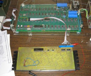
Testing the Datanetics
Finally I plugged in the MM5740 and the two 7404s and powered up again and checked for hot chips. After clearing screen and reseting, I went through the keyboard shorting each pair of pads making sure that each key worked. Then I jumpered the shift key and checked that shift characters worked. I also tested the repeat function. So far everything is working fine. The next step is to add the key switches.
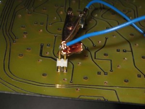
test jumper in shift key location

