Someone sent me an email asking if I could have created a PS/2 adapter that was reconfigurable in software to work with either an Apple 1 or Apple II with no hardware jumpering. I started to compose a long answer and before sending it, realized that this would be a good blog entry. So here it is.
The AVR to DIP wiring mechanism was the most difficult part of the design process, for the PS/2 keyboard adapter.
First of all I couldn’t do a software switch between the A1 and A2 pin outs without some external power switching circuitry, as the power and ground connections are different. For example, minus 12V on the Apple 1 is connected to the same pin as a data bit on an A2 keyboard.
I wanted to support S-100 and other systems with possibly different pin outs, with a standard ribbon cable. I thought about creating a user interface with the serial port to allow tweaking configuration, but decided it was too much work and could cause too much confusion, if configured wrong.
I was also concerned about increasing potential for bugs. The code for the PS/2 keyboard is pretty complex, as it is. Besides doing the bit banging to move stuff over the wire, you have to keep track of key states. Some single key state changes result in 3 bytes being transferred to the adapter. You don’t really know what is going on with the keyboard until all three bytes are recieved. When you finally decide that you have a character for the host, you then have to map a generic key code into an ASCII equivalent. A depressed shift, control or other key affects the translation.
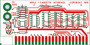
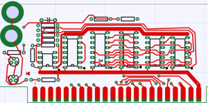
I actually laid out at least 3 variations of this board over the past couple of years. First version was a single sided PCB and A2 specific. This one can be seen at the bottom of my keyboard adapter web page. The next version was A2 specific, but you could cut existing traces and add jumper wires for other systems. Here is a CAD image of this version.
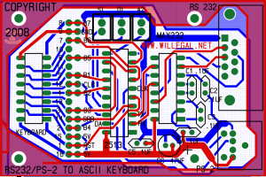
A2 version with option to cut and rewire
The Data bits are optimized for the A2 connection, not ease of wiring. Notice that I also reversed connector ends between this version and the final version. This was to make the ribbon cable connection between an A1 and this adapter more straight forward. I think that in most cases with an A1, the adapter will be to the left of the motherboard. With the original configuration this would require twisting the ribbon cable to connect correctly.
Finally, I decided I needed to create the most generic version possible, because of the desire to support systems which could have any sort of pin out. I considered making it default to A1, and then allow cutting traces and adding wires to adapt to other systems, but decided that cutting traces was destructive and not very elegant for non-A1 applications.
Once I decided that I didn’t want to force non-A1 folks to cut traces, I rearranged the pads and pin out to make hookup as straight forward as possible. I think in this regard, I succeeded. When I wired my first boards, I found it much easier to do, than when I built a wire wrap A2 keyboard to A1 converter using two wire wrap sockets. I also figured that it was going to be sold as a kit. A little extra work on the kit builder’s part, really wasn’t necessarily a bad thing. 🙂
I guess this long winded blog indicates how much I thought about the problem. The optimum design would to make a different board for each application, but it would not have been economically feasible.
I’m very happy with the result and have been exclusively using a PS/2 keyboard with my A1. The long cord and keyboard layout is much more user friendly than using an A2 plus keyboard with ribbon cable connection.

