More ACI TroubleShooting

Workshop is now in the basement, which has a decent sized table that I’ve taken over. This allows me to spread out a little bit, but the O’scope still usually ends up on the floor.

Ok, since wsander posted some AIFF files for download to the A1 from an ipod to the cassette interface on Applefritter, I had to try it. Well I barely could get it to work. Now I’m figuring this isn’t right and I’ll have to work some more on the Apple Cassette Interface. I’ve done much monkeying around including increasing hysterisis of the voltage comparator and adding a negative five regulator to it’s negative supply. All these changes made little to minimal improvement. I even put the circuit into a Spice simulator looking for a flaw. Nothing significant found. I even put the Apple II circuit into the simulator, and though there are differences, it’s not substantially different.

Finally while looking at the input from the iPod I noticed some high frequency noise on the input signal. After some simulations I determined that adding .01UF cap between the input of the voltage comparator and ground might filter out that noise, at the cost of losing a bit of lower volume capability.

After this last change I’ve been able to load wsanders iPOD files reliably. I’ve also been able to write and read cassette tapes, but the volume setting on my particular tape recorder, a vintage Realistic CTR-31, is very very critical. I’ve been able to save Apple 1 Basic, plus Hammurabi and restore it via tape. I wouldn’t call it reliable, but it can be done. I’ll probably revisit this in the future, but for now, I’m going to do some testing on CFFA-1 card, while waiting for a new batch of caps and finishing the assembly manual.

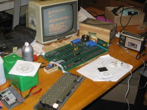
More Mimeo-1 Testing About Wrapped Up

74161 investigation

I did some further investigation into the problem with the 74161As. The problem is limited to location D-8, the other 74161 locations can be populated with 74161As without issue. Here is what I have found out about the problem with D-8 so far.

The high level of the input to D15-9 (preload) is just at 2 volts. There is a small glitch below 2 volts just before the char rate clock(CLA) raises. D15 responds by lowering VINH and things go south from there. D15 should preset VINH to high, but apparently the floating preset input drops a bit at the same time, resulting in a preset to zero. Apparently a 74161A at D8 is fast enough to occasionally see VINH drop and counts on the nearby raising edge of CLA, putting the state machine into a mess. Apparently the 74161 doesn’t have enough setup time to count at this point. The time between early VINH drop and the next clock edge is about 20ns, but that is just about at the limit of my old, uncalibrated scopes resolving power, so consider this an estimate. This appears right on the edge of the 74161 setup time spec. Apparently enough for an A part, but not enough for a non-A part, which ignores this glitch and continues on nicely.

Cassette Interface

When I first tried the cassette interface, the input signal after the AC coupling cap looked rather nasty on the scope. I have learned through some efforts to build a regenerative RF receiver that AC coupling caps should be good quality. Testing this theory, I replaced the original cap, which came from a scrap box with a new monolithic cap. Sure enough the signal cleaned up considerably and I am now able to read from the tape correctly. The only thing not working, is the READ LED. I’m going to see if I can put this small circuit into my spice simulator and see how it should work, as there is nothing obviously wrong with it, though the input signal level is pretty small. It’s possible I just need a lower power LED. I have to run one additional test on the cassette interface, prior to declaring victory on this front. This is involves typing Basic into memory, WOZ style, then saving it and seeing if I can load it back in again.

So What is Left

I’ve got a few things left to do prior to taking orders.

  • Finish testing cassette interface
  • Obtain and test new decoupling caps
  • Finish the assembly manual
  • Figure out how I’m going to pack everything for shipment
  • I should be able to complete this effort before the end of Feburary. Those who are on the wait list will get the first shot at kits. If you asked to get on the wait list, I’ll send you an email when I’m ready.

    Interesting Evening with the Mimeo 1

    As of this morning, the flakey video problem wasn’t completely solved. The current counter parts I’m using are 74161A parts, and I was hoping I would manage to find some without the A suffix locally, as they have slightly different specs. I stopped on the way home hoping to find some 74161’s at the only shop in the area likely to have such parts. I lucked out and we found enough parts in a close out bin.

    After I got home, Mike Fortuna (who works nearby) dropped by with a couple of cards to try on the Mimeo 1. First we tried out Rich Dreher’s CFFA 1 card. Not only did it work, we were able to load and briefly run a couple of classic programs. These included Apple 1 BASIC, Lunar Lander, and chess. I was impressed with this card.

    Second, we tried Vince Briel’s prototype cassette interface card, but we had less luck with that one. The behavior was similar to the Obtronix cassette card that I built up. Write appeared fine, but reading was unreliable. I’ve still more work to do on the cassette interface front. Mike says the card works with his replica-1, though I don’t think that Vince was ever able to get it to work.

    Mike and I also discussed the video problem, and we agreed that the symptoms are that of a video counter issue. It was great that Mike could stop by and help me check out the board and talk vintage computers.

    After Mike left, I swapped out the 74161As with the newly purchased 74161s and after an hour of testing, things are looking promising. It is starting to look like I might have to ask my supplier to do an exchange.

    Now I’ve got to take some time to fix my son’s Srt101 camera, which was recently dropped or at least roughly handed.

    Interesting Little Issue

    I’ve had some intermittent issues with the video display getting out of whack. Turns out the known floating inputs to the video counters were not floating high. Floating inputs are supposed to float high on 7400 series parts and the Apple 1, is designed with this in mind. I suspect I need to find a different vendor for these chips. In the mean time I’ve pulled them up and so far, things are looking a lot more stable.

    Monitor Commands Are Working!!!

    Well I did plug the keyboard in backward and fried a 74LS00 chip on the keyboard. Fortunately I have spares in my stash. Once fixed and plugged in correctly, I get a monitor prompt after reset and can enter small programs. I only now realized that the monitor isn’t really the same as the Apple II monitor and I’ll need to round up or create a manual, since the Apple 1 operations manual only lists the source code.

    The kitchen counter is the lab this week.

    Next step is to solder in the edge connector and see if I can get a borrowed cassette interface to function.

    One last editorial comment. For a long time, while working on this project, I really just didn’t feel very attracted to the Apple 1. It just seemed too primitive and lacking in features, especially compared to it’s offspring, the much more sophisticated Apple2. However, I now have to admit that I’m starting too develop a fondness for this straightforward machine. For one thing, troubleshooting problems seems to take half the time or less compared to the Apple 2.

    power up

    A ton of progress today.

    I cleaned the soldering junk off the board this morning and let it dry until I came home from work.

    I hooked up the PEM (power entry module) with no chips stuffed to see if the power supplies were ok. Powered up and checked the voltages and they all looked reasonable.

    Next I stuffed the stuff necessary for a video display. That is rows C and D plus B2 (I think that was the row B chip).

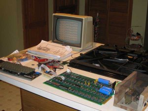
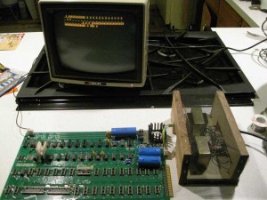
    Modified a video cable to connect to the connector on the board and got my monitor out. I plugged everything in and sure enough I got a display. Felt around the board for hot chips and nothing seemed very warm. Powered off and powered on again and nothing happened. Checked voltages and nothing. Somehow the 500 milliamp fuse in the PEM was blown. Replaced the fuse and tried again and the display came back as before. It had a bunch of pretty much random stuff, including a lot of @ signs. It was a little strange in that during initial power up, the contents of the screen would scroll up till near the top of the screen and then stop. I’m not sure if that is normal or not for an Apple 1.

    Here is a picture of the set up.

    I jumpered clear screen to +5v and sure enough the screen cleared out. Things seem pretty promising.

    I now stuffed the remaining chips, which actually wasn’t much and one bank of DRAM. I then soldered the 6502 jumpers and the address selects for PROM (0xf), 6820(oxd) and the bank of DRAM to address 0. Powering up again, I got the same screen contents. Shorting reset to ground got nothing. Ok now it’s getting late, do I call it a day or not.

    Well I decide to get out the oscilloscope. I spent a bit of time figuring out that one of my probes is dead. After switching probes, it quickly becomes evident that there is no processor clock because I didn’t connect the NO DMA jumper. That jumper is only left open if there is an expansion card attached that drives that signal. Ok a blob of solder connects that jumper. Now I get what appears to be a prompt, after reset, but also some other characters. Time to get out the keyboard.

    The keyboard is attached but when I hit reset the power light on the keyboard goes out and the computer doesn’t respond to keystrokes. I decide it’s late, time to update the blog and get some sleep. After shutting down I think I realize that the keyboard cable is connected backward. Oh well, it is late – I’ll pick it up tomorrow.

    Apple 1 Clone Build

    Fully soldered and ready to see it’s first electrons. I did leave the expansion connector off for now, it’s not essential for operation and leaving it off offers the ability to scope the bus at it’s location.

    The only surprise so far, is that the large heat sink extends a tiny bit beyond the edge of the board. Reviewing pictures of the original shows the same thing, so all is well. I was a bit worried about how the large 5 volt regulator and heat sink would go in, but no issues at all. I put a little thermal grease between the regulator and the heat sink and bolted it in with some 6-32 by 3/8″ screws I found at Home Depot.

    I’m not real happy with my decoupling cap selection, since they are much smaller than the original. I’ll probably replace them at some point.

    First test will be of the power supply without ICs installed. That will take place tomorrow.

    Assembly progressing

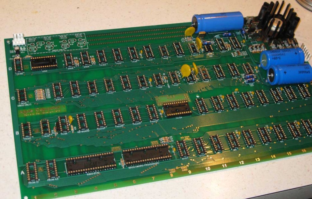
    Here is an image with the sockets in place. Note the 24 pin socket for the 74154 in the center of board is in backwards – I should follow my own instructions. 🙂

    A1 being assembled - sockets in place

    First Boards Arrive

    They are looking good, so far, can’t find any obvious faults. Will have to build one up and see what happens.

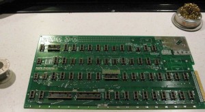
    Here are a couple of images, one of the front, the other of the back, of the bare board.

    By the way, these scanned iamges don’t really do the boards, justice.

    Apple 1 PCBs due to arrive on Monday.

    Look me up on AIM on Monday – “illegalwithaw” at 9:00 PM EST and join the group chat. I hope to be able to post images of the boards and let you know how they are looking.

    I just received the decoupling caps, the last components I had on order. Though they will be functional, I’m not happy with them, since they are so small, unlike anything used on an original. I’ll try ordering a different decoupling cap that will hopefully look a lot more like the original, and the ones I don’t use on the prototype will go into the scrap box.

    I’ve figured out the solution to the keyboard-PS/2 reconfiguration issue. I’ll put in a double row of KK type header pins. They make housings that can be individually wired and plugged in. This way, you’ll be able to make up several headers that suit your needs and just plug in the one you need. Unfortunately, it’s going to add some cost to the device, but I think it will be worth it. Here is a link to a housing as seen at digikey.
    http://search.digikey.com/scripts/DkSearch/dksus.dll?vendor=0&keywords=649-69176-028LF
    Software changes aren’t necessary for this, but I’m going to reassign outputs on the AVR, anyway, in order to clean up the PCB. I’m going to try to find time to build a prototype unit this weekend.