Apple 1 Replica Project Restarted #10

As I have been moving forward on the PCB layout, changes are getting smaller and I need to be more precise in making them. This slows down progress, as I really want to work on the PCB, only when my personal energy and patience are at high levels.

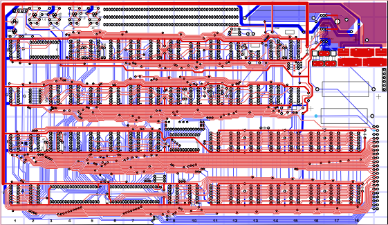
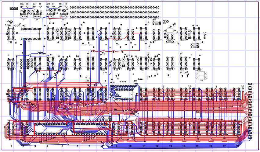
Had good energy early this morning and made progress on some touchy areas in and around the power supply. I finally feel that the back copper layer is starting to look close to where I want it. Changes to the back copper from here on out, are going to be very minor. In fact, on the back copper, I’m thinking of taking a shot at rounding off corners on the small traces, which is one of the last tasks for this layer.

On the front copper, before declaring victory, I want to do some trace spacing tweaks, especially in the busy areas between chip rows A & B and also B & C.

Front silk screen is pretty good, but I will improve character to character spacing in a couple of text strings and also improve the shape of the decoupling capacitor symbol.

My first pass through a PCB vendors DFM check returned a number of issues, I’m working through.

Besides circuit design reviews, I need to do a review of hole sizes – nothing worse than a hole too small to fit the designated component.

Regards,
Mike Willegal

Apple 1 Replica Project Restarted #9

A general update.

By now, I have already acquired or have sources for almost all of the components, though I am still working out the exact source for some supposedly common parts like capacitors. Even the easy stuff hasn’t been easy on this project. For example, the A1 used a lead spacing of 300 mills for decoupling caps, which is not common today.

Unfortunately costs have risen to the point where my cost per unit has exceeded the current selling price for an A2 motherboard replica kit. I don’t know how Steve Gabney sold his kits at the price he did. I suspect he isn’t responding to emails because his costs equaled or exceeded his selling price making his efforts a losing proposition in business terms. I hope that my final selling price doesn’t scare off too many hobbyists. At this point, I’m toying with either a 555.55 or 666.66 number. I may use the second number for assembled units and the first for kits.

Once I set the price on these units I will not budge. Lowering the price on the A2 rev 0 replica, like I did, really hasn’t greatly affected sales. Regarding the cost of the A2 rev 0 replica, I am planing on raising prices, a bit, once this batch of kits is sold. I still am in the red on that project. It’s not worth repeating the effort of gathering components for these complex kits unless there is some kind of return on investment. The only good thing concerning costs, is the recent sale of an original A1 for $50,000. That should put things in better perspective for buyers. Also I’ve only seen a single original A2 rev 0 on eBay all year. I would expect that some demand is building after a couple A2 rev 0’s went for what I consider bargain prices in 2008.

As far as the PCB layout goes, I have the first pass completely done. I’m in the first fine tuning pass. I’ve had one of the online PCB vendors run their free DFM check on it and it’s found a few issues, which I need to deal with. To give you an idea of the difficultly and the attention to detail I’m putting into this project, the CAD file on this project is currently 50% larger than the final A2 rev0 CAD file, even though there are only 2/3 the number of components. In real numbers the CAD file is 500K bytes long versus 336K on the A2 rev 0.

For those that wonder how they will be able to tell my replica from an original, I put a small logo in the copper layer on the back corner of the board. Here is what it looks like on a rev 0.
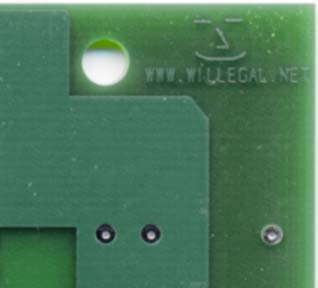
replica-logo

Finnally I started a webpage to be used as a source of information on the A1 replica. It is at http://www.willegal.net/appleii/apple1.htm

Apple 1 Replica Project Restarted #8

Quick update on major areas.

PCB:

First pass of the following layers complete.
bottom copper
top copper
top silk

Up next:
Top solder mask which has some unusual features.

Pending:
Second and then third passes through each layer (these should go much more quickly than the initial pass did)
PCB vendor DFM (design for manufacturing) check
Net list check against schematics
Rounding off trace corners
Final Pass
Final DFM check
Final Net list check

Parts:

Some parts have been received
Others on order
Still determining best vendor for several key parts.

Example of what goes on when sourcing parts. I spent several hours yesterday reviewing the board edge connector and evaluating sources. If I was doing a new design I would just pick an appropriate part and layout the board to suit. In the case of a replica you need to determine the specifications of the part, find the part that fits the specs and finally find a source.

Overall Costs:

Note that some rough estimates on PCB cost indicate that the gold finger edge on the board will raise PCB cost more than I initially thought. Costs continue to look higher than the Apple II due to to PCB, more expensive obsolete parts than the A2, and the power supply. The two transformers alone cost over $40 for a single Apple 1.

Apple 1 Replica Project Restarted #6

Work is moving forward on the silk screen layer. I was hoping that I could directly leverage fonts created for the Apple II rev 0 replica. The Apple 1 fonts are different enough from the Apple II fonts, that I am not satisfied with the default results of just porting the A2 fonts over. Therefore I’m working on improving the match with the original Apple 1 fonts. One other challenging aspect of the silk screen is my CAD program doesn’t support proportional character spacing. This is going to cause me some extra work in order to get the character spacing right, as it did on the Apple II rev 0.

With the exception of the gold finger connector, which hasn’t been added, the copper layers are pretty good right now, probably good enough for most people. However, I can see some areas, particularly on the front of the PCB that I’ll revisit once the silk screen has had a first pass. Keep in mind that my goal is 10 mill (1/100″) accuracy of reproduction.

I also did some rough pricing of PCB fabrication and found that the gold finger connector will cause a surprising cost increase over the Apple II rev 0 PCB, despite the similar board size. The cost of the Stancor transformers and caps for the power supply are also driving up cost. Despite a somewhat smaller parts count, his project is definitely starting to look more expensive than the A2 rev 0.

Once I get all the parts kitted, I plan to offer a complete parts kit to Obtronix bare PCB owners. Eventually I’ll offer bare PCB boards, and parts for Apple 1’s, similar to what I’ve offered to those interested in the Apple II rev 0 kit.

regards,
Mike Willegal

Apple 1 Replica Project Restarted #5

icomparision-mage-of-board
The front and back copper layers are starting to look pretty good. I can still make some improvements, but I’ll take a break from focusing on those layers and do some work on the silkscreen layer. I feel comfortable enough with progress that I’ve started ordering enough parts for about 12 boards. Attached is an image of the front copper and solder mask artwork colorized and put next to the same image of an actual original board. This kind of comparison can help with accuracy. In creating this comparison image, I found 3 to 4 things that need correcting. Can you find them? Note the hard corners of the digial traces as compared to the actual board. I intend to soften those corners, before going to production, but it will be one of the last things that I do.

Apple 1 Replica Project Restarted #4

I’m making progress, have aligned a lot of the back. Check out these two images, but keep in mind that I’m not done tweaking.
My layout overlaid over a photo of the corner of an actual Apple 1.
a1-replica-pia
My layout overlaid over a photo of the corner of an obtronix clone.
obtron-replica-pia

Apple 1 Replica Project Restarted #2

This board is proving to be tougher in some respects than the Apple II. I’m glad I did the II, first. The Apple 1 has slightly smaller traces that are closer together than the II. Bus layout is also more difficult to replicate as the II had most of the busses running under the rows of RAM/ROM and Slots, which made for fairly easy alignment between the rows of pins.

The board is also slightly larger than a II, with a gold finger connecter (more $$). With the rarity of parts, plus power supply circuitry, I wouldn’t be surprised if this going to cost as much or more to put together than the II.

Also I plan on building a batch of the PS2 to ASCII keyboard http://www.willegal.net/appleii/appleii-kb-int.htm interfaces to go with this project. This will provide an easy way to download software, such as Basic from a PC into the machine without having to deal with a cassette port.

One other point for those that have seen the Obtronix replica. That was a very well done project. However, I’m expecting that my Apple 1 PCB will have even more accurate routing of traces, as well as a more accurate silkscreen. Check out my rev 0 replica to actual comparison page http://www.willegal.net/appleii/appleii-compare.htm to see what I expect to do for the Apple 1.

I estimate that this project will take 4-6 months, possibly longer to put together, so if you want a nice project to fill in some of the time, while you wait, Apple II rev 0’s kits are available and ready to ship. 😉

I’m able to wire in two to three 16 pin chips a day. Attached is a snapshot showing current state of the project.

Regards,
Mike Willegal
Picture 3

Apple 1 Replica Project Restarted

Using available off the web images, I had already done some preliminary work on the PCB layout. However this was put on hold, sometime back, due to lack of really good images of the original. It was too hard to work with the relatively low res images, that I had. Last week, an Apple 1 owner provided me with hi-res pictures of the front and back of an original Apple 1 motherboard.

For some bizarre reason, I derive a lot of satisfaction from the process of reproducing an original board. Now that I have an quality original image of both front and back, I can hardly stop myself from working on it. I will be able to leverage experience and CAD libraries from the Rev 0 project, so I’m hoping that this project moves along a little quicker than the rev 0 project, did. To make up for this, I do expect a lot of challenges obtaining some of the rare components needed to build an operating Apple 1.

I do hope I can come up with an image of an original board, without components mounted on it, which would remove the guesswork of routing traces hidden by components. However I’m not considering this a show-stopper.

Regards,
Mike Willegal