A few days ago, I was searching through my small personal archive of Apple II floppy disk images, looking for an Apple II clone of Colosal Cave. As fate would have it, among those images, I ran across a program called “THEGREATAMERICANPROB.MACHINE”. Vaguely recalling it being a fun program from the “old” days, I started up an Apple II emulator, loaded the DSK image and ran the program. Here is a screen capture
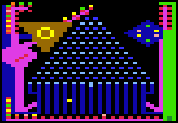
GREATAMERICANPROB.MACHINE
and a movie of the program in action.
Just as I sort of remembered, it was a pretty cute Apple II low res color graphic animation. However, when the credits rolled, I discovered something totally unexpected. It was written by none other than Bruce Tognazzini. Tog, as he is now known, is now a respected authority on user interface design.
Having had a brief email interaction with Tog a few years ago, and knowing he was quite approachable, I decided to send him a message. I let him know that this old work wasn’t forgotten. I figured that he would appreciate that. The response I recieved, had some quite unexpected news. Here is Tog’s reply.
Thanks. It was when Steve Jobs saw that program that he decided to hire me. It was the first ever full-screen animation done on the Apple II.
I sent him another message thanking him for his reply and asking him if he minded if I shared it on my blog. He responded with more details about how “THEGREATAMERICANPROBMACHINE” helped get him hired at Apple.
Not a problem. Specifically, I took a piece of code I’d written that added a new command to Integer BASIC down to Apple to show Steve. After selling him on that, he asked me what else I had done. I showed him the Probability Machine, throwing it up on Apple’s large-screen Advent projector. He got really excited, left the room, and gathered up everyone he could find in the building. (Apple was still all in a single building in those days.) I was quite surprised it caused so much excitement; I had no idea I’d pulled off something that, at the time, was a breakthrough. A week or so later, Jef Raskin called me up and said that Steve thought we should talk. I assumed he was going to want to buy some more of my software. It turned out, he and Steve wanted me,
-tog