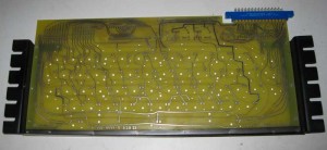
I finally recieved all the parts I need to complete assembling and testing of the reproduction Datantics PCB.
I carefully drilled 1/16″ holes to match each bracket to a couple of mounting holes in the PCB. Then I inserted the eyelets and used the eyelet setting tool to set them and secure the bracket. I then drilled the rest of the holes, and set the rest of the eyelets.
You have to careful with this work. Two eyelet sizes are needed, keystone #26 where you only have one bracket to go through. #27 in the four holes where both brackets overlap. I used an inexpensive eyelet setting tool that I got from volcano arts. After completing this task, I would say that the holes in the PCB are slightly bigger than optimal for the 1/16″ eyelets. Despite this, the eyelets worked out fine in my board. Have I mentioned that one of the biggest problems I have with these reproduction boards is getting the hole dimensions right. This is especially hard when I don’t have engineering drawings for the original parts.
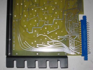
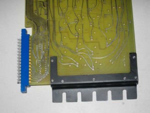
more pictures of the brackets
back of board
The blue edge connector seen in these photos will be wired to a ribbon cable for connection to my Mimeo motherboard. It is Digikey part number S3345-ND. The key thing with these edge connectors is the spacing which should be .156. There are 15 positions per side for a total of 30 contacts. I got the edge connector dimensions right, the connector fits perfectly.


