The six input ports on the SCELBI each have an independent 8 bit data bus that is not connected to anywhere else, except that ports dedicated input circuit. Like the output ports, the input ports are also implemented using 78S11 sockets and 86CP11 plugs. The sockets contain 1 ground wire at pin 11 and 8 data wires from pins 1 through 8. There is nothing connected to pins 9 and 10.
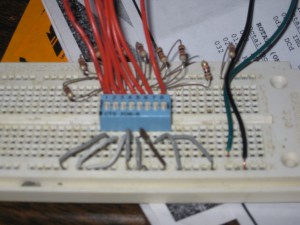
Since 9 is not connected, I decided to reuse the test cable I made for output port tested, except change around the breadboard to control input lines, instead of monitor output lines with LEDS.
In this case I connected the 8 data lines to 1K ohms pulled up to 5 volts. Since 5 volts doesn’t exist on the cable, I wired the 5 volts from my 5 volt power supply. Using a series of 8 DIP switches I could connect any one of these lines to ground, as I pleased.
Now I basically repeated what I did for the output port test, only using the INPUT instruction and dumping the contents of the accumulator to memory to verify that the read was successful.
Note that after running this test, I realized that the input signals are already pulled up on the input board, so the pullups in the test rig aren’t actually necessary.


