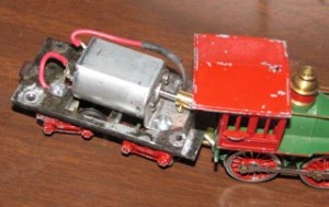
I generally followed Al Muellers recommendations for replacing the drive line – though I did have difficulty drilling and soldering the music wire into the brass rod on the engine side. The tender side was easier, since I drilled the smaller hole and used it as a pilot hole for the motor shaft. This caused the drive wire to be lined up with the shaft, even if it wasn’t perfectly centered in the brass rod.
The shortened drawbar was cut out of scrap PCB material. The copper side is cut, so that there is no short circuit between the tender and the cab.
The other thing I changed was mounting the Nichibo PC-130 motor. I found I had a couple of screws that fit the mounting holes on the face of the motor. I presume that these are a metric size. I decided to use some scrap sheet metal to make a mount. It is bent at a 90 degree angle and using a #6 screw, mounted to the tender floor, opposite the hole that is used for feeding track power back to the tender. This provides a solid mount that, if necessary, can easily be removed or adjusted. I will eventually add DCC, but not sound, as I am looking at developing an external sound system, which will be able to produce far more dramatic effects that the small speaker in a tender could produce.
The Nichibo PC-130 motor produces incredibly improved low speed operation. I’m just amazed at the dramatic difference that this made. I haven’t yet calculated scale top speed using a traditional 12 volt power pack, but I’m guessing that it is way below capabilities of a real 4-4-0. Since I’m only modeling the yard and port, where speed would be low anyway, I’ll probably live with it.
I have some more things to do with the locomotive.


Well done, Mike!
Al Mueller