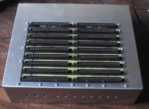
I’ve been working on moving my SCELBI 8B to one of Corey’s custom chassis. Here is what it looks like at the moment.
I figured I’d share some SCELBI chassis preparation tips here.
1) To prevent rub marks, use masking tape to protect any areas of the sheet metal that may experience contact with your tools.
2) Keep in mind that during this period, American engineers exclusively used imperial dimensions.
2) If you are converting a BUD AC-413 chassis you must first cut out the backplane area and drill holes for the I/O ports. If you have one of Corey’s chassis you can skip to step 6.
3) I recommend, making patterns for both top backplane opening and rear I/O connectors. Then attaching the patterns to the chassis when making the cuts.
4) The hole in the top for the backplane is set back 1/2″ from the front and centered from side to side. The dimensions Corey used for top cutout of the 8B is 6.375″ deep by 8.875″ wide. The 8H is 1 slot shorter in depth. Slots are spaced by .75″, so 8H would have .75″ less depth. 6.375-.75 = 5.625 There isn’t a lot of room for error when mounting the backplane, so try to be precise as possible. If done right, the edge connectors will just fit through the opening, when the backplane is mounted underneath. If you have doubts, you can add the edge connectors to the backplane and measure the area needed to fit them and work from there.
5) The I/O holes in the rear can be punched out with a type 732 GreenLee chassis punch, sized 1 11/64″. Be aware that type 732 comes in different sizes. Prior to punching you need to make a series of 1/2″ holes to mark the center of each opening. These holes are on 1 3/8″ centers. There is more on these dimensions on this blog posting.
6) Once you have pilot holes for the I/O connector and the backplane opening cut out, you can punch out the final I/O connector holes. When using the punch, the cutting edge should be on the outside of the chassis, so you don’t mar the exterior surface. Don’t mount the I/O connectors until all cutting on the chassis complete. I don’t know if it makes a difference, but I lubricate my Greenlee cutter with spray silicone lube.
7) If you have a front panel, you can use it as a guide for the toggle and push button switch holes. Simply clamp it to the front of the chassis. There should be even overhang on the sides and the bottom of the chassis should be flush with the bottom of the front panel. The holes for the toggle switches are 1/4″ and the push buttons are 9/32″
8) Mounting the backplane is one of the most critical aspects of building a SCELBI chassis. Solder on all your edge connectors before proceeding, but do not mount the card supports.
9) Note that the current version of my 8H backplane does not have predrilled mounting holes, so you will have to drill holes through both the backplane and chassis together, instead of using the backplane as a guide.
10) In order to drill the backplane mounting holes, position the backplane on the underside of the chassis. The edge connectors should protrude through to the top of the chassis. I use card stock to shim each side of the backplane so it is centered and doesn’t move. I use #6 screws to mount my chassis, so I used a 9/64″ drill bit. Don’t confuse the holes for the card supports with the chassis attachment holes. For the 8B, I start by using the backplane as a guide to drill 4 holes in the chassis. These holes are the ones on each back corner, and the ones on each side closest to the front.
11) I then move the backplane to the top of the chassis and use the holes I just drilled to correctly locate the backplane. Put 4 screws through the 4 holes you just drilled to keep it in position. If you have an 8B, you can use the backplane as a guide to drill out the remainder of the chassis support holes.
12) Note that the support of the front edge of the backplane is not by holes through the backplane, but by the nuts of 7 supporting screws which overlap the front edge of the backplane. These 7 holes must be located at the edge of the backplane, so that one edge of nuts will hold the backplane in place.
13) Any burrs left on the holes can be scrapped off by twisting a sharp, large bit in the center of the hole. Do this by hand, not in a power drill. The aluminum is soft and it doesn’t take much to remove these burrs.
14) Remove the backplane before you add the Amphenol I/O and power connectors. The rings that hold these on, do not seat completely and it is an exercise in frustration to try to make it so.
15) Now that all the holes are drilled, mounting the backplane to the bottom of the chassis is pretty straight forward. Just don’t over-tighten the nuts or you could crush the substrate.

