Easy TTY Emulation on an Apple ][e

Back in 2015, I partially described how I used an early Apple serial card in an Apple ][ to provide a “glass” TTY emulation in order to check out some of my SCELBI software and interfaces. Since I don’t have a real TTY, I always had to set up the Apple ][ and download an emulation program via cassette tape interface in order to test the SCELBI with an TTY interface. Over the years, this has been an annoying bit of hassle, mainly because I usually forgot exactly what version of the software that I needed to download, exactly where in memory to download it, and what slot to put the serial card into.

I knew that I could create a turnkey power on and go solution by designing and building a custom Apple ][ peripheral board. I just needed to copy the current loop interface from the Apple Serial card to a Superproto board and drive it with the Superproto’s 6522 VIA interface hardware. I knew I could easily port the program I had already written to run right out of the Superproto’s EERPOM. I first thought about doing this years ago.

Finally I started to do something at the beginning of this year, when I ordered the few required hardware components that I didn’t have in my stash. These parts came in right away, but, until now, I haven’t found the time to build up the board and port the software.
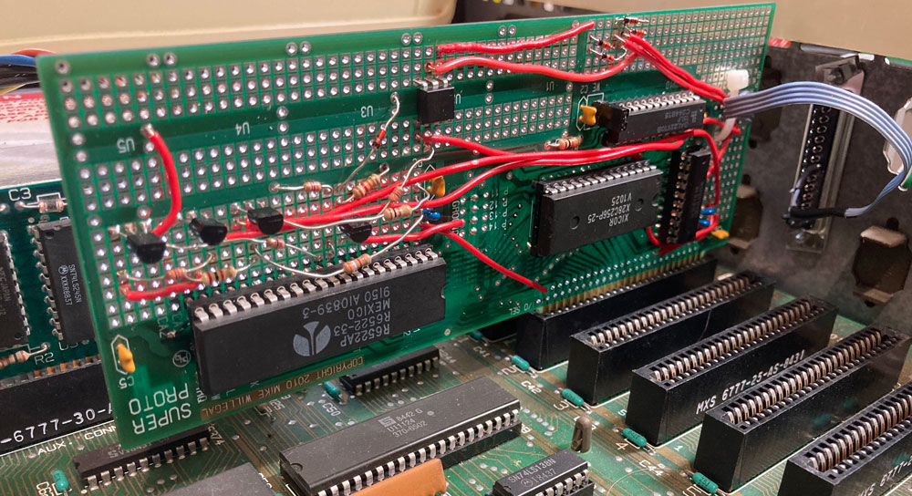
TTY Card
TTY Card

Well, I finally found the time to get this project working. I think the result is pretty cool. To connect a TTY with a 110 baud current loop interface to my SCELBI, I just connect the Apple ][e to a monitor, the SCELBI and power it up. No need to bother with floppy disks or cassette interfaces, or anything else. Since this card looks like a Disk ][ to the Apple, the Apple will automatically boot the TTY application, which resides in the Superproto’s EEprom.

I could potentially add logging, paper tape emulation and scroll back capability to this application, but I probably will not proceed with those ideas, at least anytime soon.

One other thing I might do, is create a version of software that will work at 45.45 baud and the Baudot charactor code, so I can use it with RTTY applications. I have done a simple version of this software for the Apple serial card, so it shouldn’t be too hard to port over. Since the Superproto supports multiple banks of memory in the EEPROM, I can use the same board and just put the RTTY app in a separate bank, and use the bank select jumpers to switch between TTY and RTTY applications.

Someday, I might make a custom card for this design, but I’m not going to do this unless I hear about some kind of demand for such a card.

Let me know if you are interested in seeing more details of the software and hardware design.

SCELBI Fast Loader Peripheral

Booting the SCELBI without an integrated EPROM boot loader/monitor can be an extremely difficult and time consuming process.  The first issue of the SCELBI newsletter described a very simple peripheral that makes this process easier.  I’ve known about this simple device for years, but until now, never built one. Well it turns out that I should have built one when I built my SCELBI-8H. It makes for a huge improvement in data entry capabilities of a SCELBI that doesn’t have a EPROM monitor, like my 8H, as it was initially constructed.

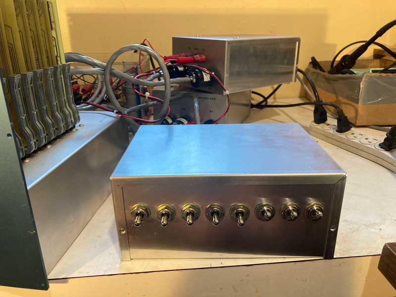
SCELBI Fast Loader
SCELBI Fast Loader

The fast loader peripheral is a simple device that relies upon a tiny four byte long program which can easily be toggled into memory with the SCELBI’s front panel.

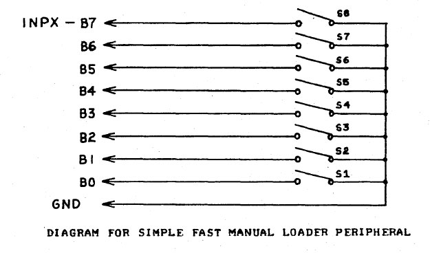
The device is connected to any input port with a standard SCELBI peripheral cable. There is already a pull-up on each input, so all that needs to be done, is to either leave the input floating, in which case the SCELBI’s internal pull up resister will pull the input level high or connect the input to ground, which will force the input low. The operator sets each input to a high or low state with a simple DPST switch.

Fast Loader Schematic

The way this peripheral is operated is as follows.  Using the front panel, the operator toggles the four byte long, fast loader program into memory, starting at location 0, and then sets the H and L registers to point to where the data needs to be written.

When run, the fast loader program will read the input port connected to the fast loader, writes the data to memory, increments the L register and then halts.  Once the program is started, the operator enters a RST 0 instruction into the SCELBI front panel toggle switches.  While still halted, the operator enters the data to be written into the next memory location into the fast loader toggle switches.  The operator presses the interrupt button on the SCELBI front panel and then the run button.  The program will jump to zero because of the RST 0 instruction that is set on the front panel. The program at location zero will read the input port, deposit the data to memory pointed to by the H and L registers, increment the L register and then halt again. The process is repeated until the operator has entered all the desired data into the SCELBI’s memory.

The fast loader program follows. This version assumes the fast loader peripheral is connected to input port zero, but other ports can be used by changing the INP instruction.

Line Addr.  CodeBytes   Source LineLine Addr.  CodeBytes   Source Line
—- —— ———– ———————————-
01                    START:ORG 000#000
02 00-000 101 INP 000 ; read port 0
03 00-001 370     LMA ; save to memory
04 00-002 060         INL ; increment L
05 00-003 000         HLT ; stop

 This program doesn’t handle the case of register L wrapping, but a few more instructions could be added to increment register H, if L wraps. Most boot programs should be designed fit into a single page, so this should not be necessary.

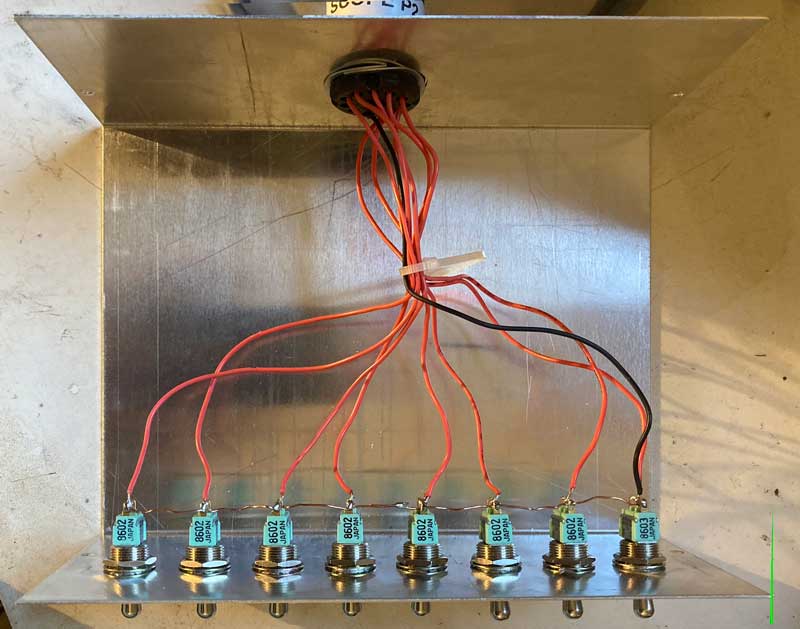
Here is a picture of the inside of the fast loader that I built. You couldn’t possibly come up with a simpler design for a peripheral device.

Fast Loader Interior

Debugging the SCELBI Power Supply

I had a bit of trouble debugging the 5 volt side of this power supply. First symptoms I noticed was an inability to regulate under load. As the load increased the output voltage dropped significantly to the point where the computer would not work. In my mind, this probably meant that the regulator portion wasn’t working.

These sort of Power-One linear supplies use a uA723 regulator to do the job. You feed reference voltage and output voltage (usually divided by a resistor network) into the regulator and the output of this chip controls one or more power transistors to supply the desired voltage. You can find more about these supplies on this nice Power-One hacker page.

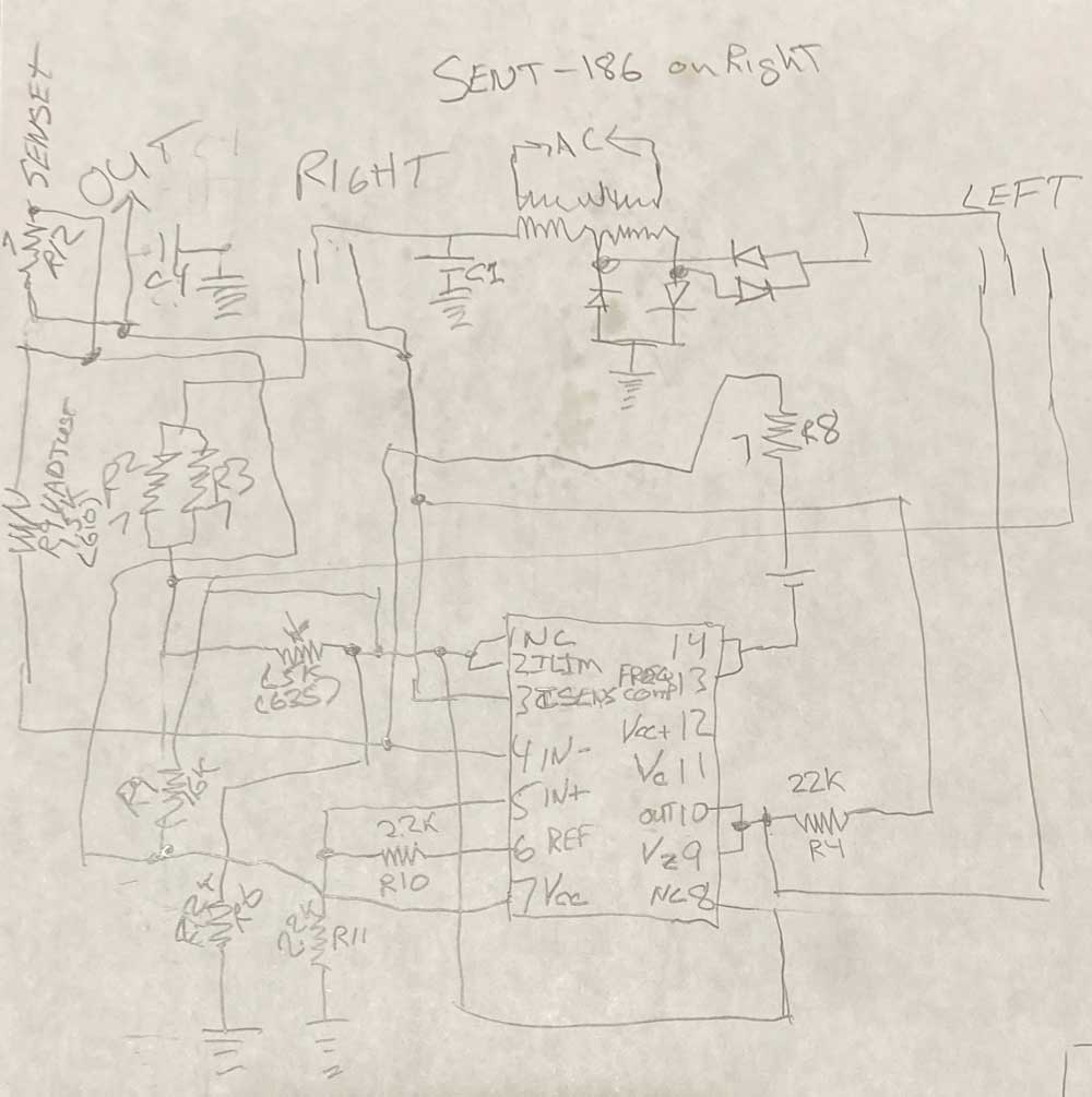
Though the Power-One linear supplies are all similar in design, they differ in details. I made a schematic of this particular power supply so that I could properly debug it.

Power-One Schematic
Power-One Schematic

After much probing, I could find no issues with the regulator circuit or the regulator chip. This really confused me, as the power supply regulation wasn’t operating correctly. After some hard thinking, I wondered if the problem might actually be with my measurement. Since my oscilloscope was broken, I switched my DMM to AC mode and as soon as a load was applied, I detected a several volts of ripple. Using a DMM to check ripple by putting it into AC mode is a trick that I learned somewhere along the line and has come in handy a number of times.

Realizing that most likely the smoothing capacitor, wasn’t smoothing, I jumpered in a fairly large capacity smoothing capacitor that I had in my stash. Sure enough, the ripple disappeared and the power supply output remained stable under different loads, just like it was supposed to.

I ordered an appropriate replacement and a spare. I replaced the smoothing capacitor and the power supply worked flawlessly for the remainder of this original SCELBI-8B’s checkout.

This isn’t the quite the end of the story. After I returned the system to the owner, the power supply failed again. Since symptoms were the same as before, I thought that perhaps the replacement capacitor failed during shipping, I sent a second capacitor to the owner, who wired it in parallel to the replacement cap, which solved the issue (again). Whenever I order parts, I almost always order spares, as shipping is often more expensive than the parts themselves. Having a spare on hand certainly was helpful this time around.

I’m not sure what happened during shipping of this system. Generally, I’m pretty reluctant to repair old computers, because of the high risk of new issues appearing during return shipping. I only took on this job because of the rarity of a SCELBI-8B and the chance I would have to further document an example.

Details of a Factory SCELBI Power Supply

SCELBI Power Supply

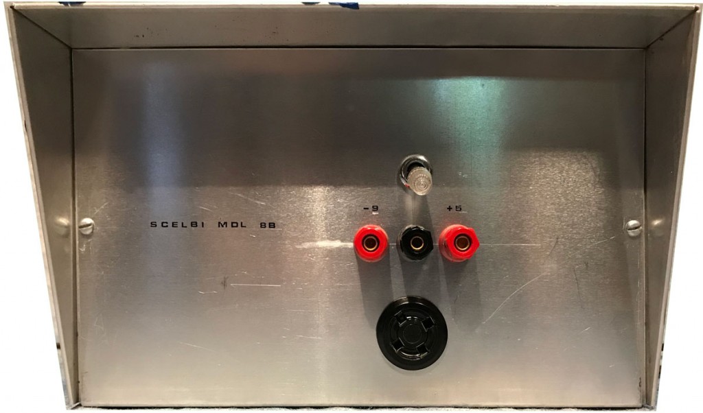
Here is the front of the factory power supply that is part of the SCELBI-8B system described in the last post. A simple on-off switch, three banana plugs/binding posts, (+5 volts/-9 volts/ground) and an Amphehol 4 pin socket for connecting power to the chassis make up the controls and connections on the front. On the back is a fuse and fitting for passing the AC power cord through the back of the chassis.

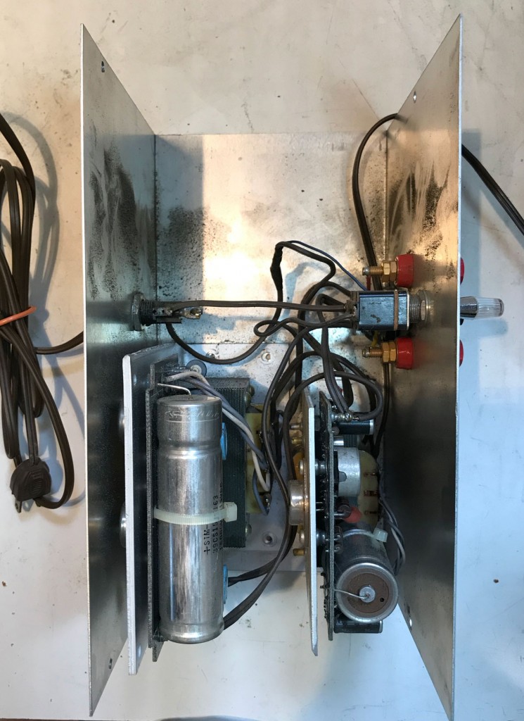
The inside reveals space at the top of the picture for a 110 volt AC fan which is bolted to the cover. The cover has ventilation holes drilled in both ends to allow the fan to draw in cooling air. Two Power-One supplies make up the power supplies. One is 5 volts and the other is a Power-One 12-15 volt supply modified to output 9 volts. The positive output of the 9 volt supply is connected to the negative output of the 5 volt supply which becomes ground for the system. The negative output of the 9 volt supply becomes -9 and the positive output of the 5 volt supply supplies +5 volts to the system.

All in all, the whole thing is an extremely simple affair, the only complication being the changing of a resistor in order to covert the 12-15 volt supply to a 9 volt supply. This unit did not actually use banana plugs for power delivery to peripherals, but ordinary hook-up wire connected to the binding posts.

In my next post I will describe the problem with the power supply and how I resolved it.

Original Fully Operational SCELBI-8B

SCELBI-8B

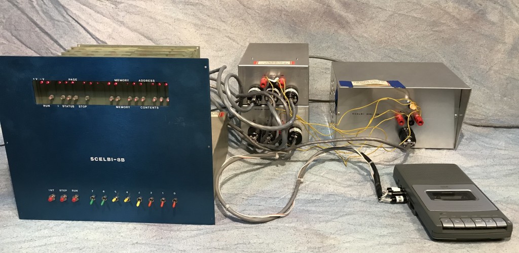
What we have here is a complete, original operating SCELBI-8B. It includes 12K SRAM, 4K EPROM loaded with MEA, a TTY interface, a cassette interface and on the right, an extremely rare SCELBI factory power supply.

I was asked by the owner of this system to get it working and I agreed to do the job. After setting it up, the only problem I could find was a bad smoothing capacitor on the five volt power supply. I will write up the power supply diagnostic process in a future blog posting.

I ran SRAM tests, and a number of applications on this system, including most of the features of MEA as well as SCELBAL. The owner was concerned about EPROM contents, so I wrote an EPROM verification program, which it passed with flying colors. Once the power supply was fixed, the system ran these diagnostics and applications in several sessions covering several days without a single glitch. SCELBI’s usually are pretty reliable machines and this one was no different.

By the way, I will be posting the EPROM verification program at some point on my 8008 application page.

However, there has been one snag. After I returned the system to owner, he reported that it didn’t work. The symptoms sound exactly like the original power supply problem, so I hope that this can be resolved relatively easily.

I really tend to shy away from doing repairs for the reason that a lot can go wrong while shipping an old system around the country. For example, quite a few years back, I repaired an Apple II, rev 0 motherboard which had three different faults. By the time it got back to it’s owner, a forth fault occurred. Even though I did this repair as an experiment and didn’t charge the owner anything, he appeared quite annoyed with me. Fortunately, in that case, based on the symptoms, I was able to correctly guess the root cause of the forth failure and get that machine running again, without having to ship it again.

Despite the challenges associated with repairing old computers, getting a chance to get an original 8B running and document it was too exciting to pass by. Though I have heard of one or two other original SCELBI-8Bs that partly work, this is the only one that is completely working, at least that I know about

Well it’s actually not working at this instant, but I’m certain that with a little more effort, it will be running, again.

Some Exciting News to Be Revealed Soon and Tek 465 Repair Fail

Keep following this blog as I reveal some details of the repair of an extremely rare computer. I think that this system is currently the only fully operational original system of it’s kind in existence.

After a bunch of effort and a number of replaced parts, I have decided that my Tek 465 might possibly have a bad CRT. I’ve decided to put this repair effort on the back burner and ordered a INSTEK GDS-1054B digital scope. It has 4 channels and 50 MHz speed which should be sufficient for most of my hobby purposes going forward. I’m not real excited by the 50MHz speed, but given the price point that I was shooting for, it was either that or drop down to two channels to get a 100MHz unit at a similar price. I figured that I would use the extra channels more often than the extra speed, so I went with the 4 channel 50MHz unit. One problem is that it doesn’t support Z mode, which means I don’t have a way to run my SCELBI CRT Interface until I either get the Ten 465 working again or get one of my Heathkit OM-14’s restored. Somehow I ended up with three of those Heathkit scopes. I intend to restore two and use the last one for parts.

Finally watch my demonstration of an operating SCELBI-8H with Digital Group Video card at the Virtual VCF that will be shown on youtube tomorrow: .https://www.youtube.com/watch?v=7YoolSAHR5w. I think that this shows that with some effort, the SCELBI-8H can be transformed into a pretty useful computer.

More Tek 465 Debugging

Getting my Tek 465 operating correctly again has been quite an involved exercise and to be honest, I considered giving up on it. As related in my previous post, after replacing a questionable electrolytic capacitor, it didn’t come back to life. What really made me consider giving up, is that the problem appeared to be in the high voltage section that drives the tube, as the power supply started making some buzzing noises and the display disappeared. I don’t have proper probes for handling those high voltages and didn’t want to get myself into a dangerous situation.

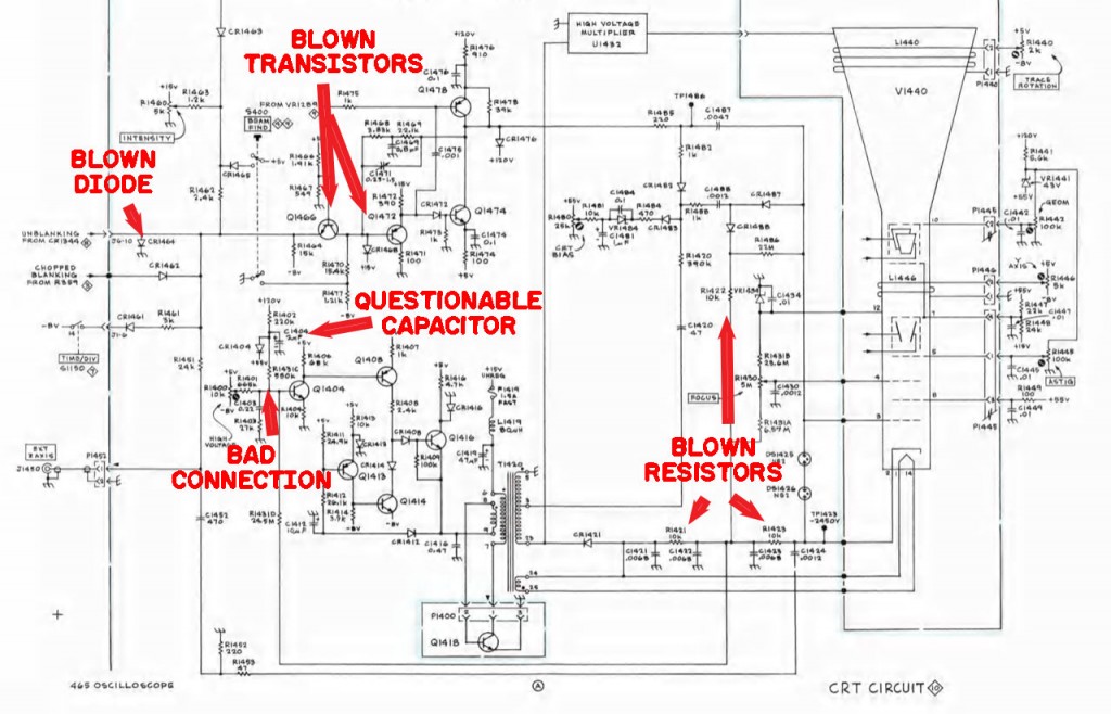
However, before giving up, I decided to take a look, as best I could. With power off and no high voltages present, I did some poking around with a meter, using the diode checker function to check out transistors and diodes and ohm meter to check out resistors. After a lot of probing, I found that 10K resistors R1421, R1422 and R1423 were all open circuit. They must have all blown like fuses.

After replacing them, I found that the scope still had issues. What could have caused all these resistors to fail, I thought. Eventually, after examining many more components, I found that one of the connections to a custom film resistor was open. This was near the capacitor that I had replaced. I think it must have had marginal contact all along and I must have broken it when replacing that nearby capacitor which connects near one end of this resistor package.

465 Woes
465 Woes

This resistor is used in the high voltage switching supply as part of the feedback circuit. I think this open connection caused the supply to run away and generate too high a voltage which caused the buzzing noise and must have blown out the resistors.

Fixing this contact and replacing the blown 10K resistors seemed to have restored the high voltage as the display now started working and didn’t buzz any more, however horizontal blanking didn’t work correctly. The blanking circuit was less scary to me, as it didn’t involve super high voltages and I dived in.

Probing the blanking circuit, I found two bad transistors, Q1466 and Q1472. It turns out that Q1472 could be replaced by an ordinary 2N3906, but Q1466 used a Tektronix part number 151-223-0. I found that equivalent replacements are either a 2N4275 or 2N5769, depending upon who you believe. However I didn’t have either in stock. I found the same part was used elsewhere in the scope and decided to try a swap to see if I could get further in the debug. It’s convenient that the transistors in this scope are socketed.

After swapping, I found that I still had a problem in this part of the circuit. After much digging, I finally found that diode 1464 was also blown. Well it was actually internally shorted and acting as a low value resistor instead of a diode. This was another part that I didn’t have in my stash, a Tek cross reference page called for a 1n4244. It turns out that this is a diode with a 750 pico second recovery time, rather fast, which I assume is necessary in order to switch the blanking on and off quickly.

At this point, I decided to call it a night and to find correct replacement parts before preceding further. I found that someone in Oregon had the exact Tek part number 151-223-0 for Q1466 and I found another vendor had the 1N4244, though I had to order some additional parts in order to make up a minimum order for this particular order. I have been meaning to build a SCELBI quick loader box and needed some toggle switches for that application, so I tacked an order of 8 toggle switches onto this order to make up the minimum amount.

Last, I swapped back the good 151-223-0 to its original location and set aside the scope. You don’t want to be swapping these parts around willy-nilly, as it can ruin calibration.

It will be interesting to find out if the scope will be finally be made good when the new parts arrive.

465 ‘B Trigger Holdoff Failed Again, Fixed, New Failure

My faithful Tektronix 465 scope failed again. This was a repeat of the B trigger holdoff problem, that mysteriously fixed itself a few weeks ago. Of course problems like that usually return and it didn’t take long. This time around, it didn’t fix itself.

I didn’t know much about how this scope worked and I had to spend a considerable amount of time over several sessions before I finally tracked down the root cause. It turns out the triggering circuits of this kind of analog scope are made up of a number of transistors that are often configured to operate over very specific voltage ranges that are set up by resistor divider networks. Frequently diode or gates are used to combine signals, which makes it hard to determine exactly why a signal is behaving the way it is. When something goes wrong, it’s not always obvious to the casual investigator what it might be.

Anyway, I eventually tracked the problem down to a bad transistor in the B trigger holdoff circuit. This is transistor Q1052 in the schematic. I verified the bad transistor by swapping it with Q1054, which is the same type. The nature of the problem changed, indicating that one of the transistors was bad.

B Trigger Holdoff Circuit

The part number listed in the service manual is 151-220-03, but I found another TEK manual with cross references that listed a 2N3906 as a “similar” part. I had some of those on hand, so I swapped out the bad part and B Trigger started working again. Since this seemed like a pretty basic PNP transistor application, I was planning on trying the 2N3906, if the cross reference recommended something else that I didn’t have.

Capacitor and Resistor

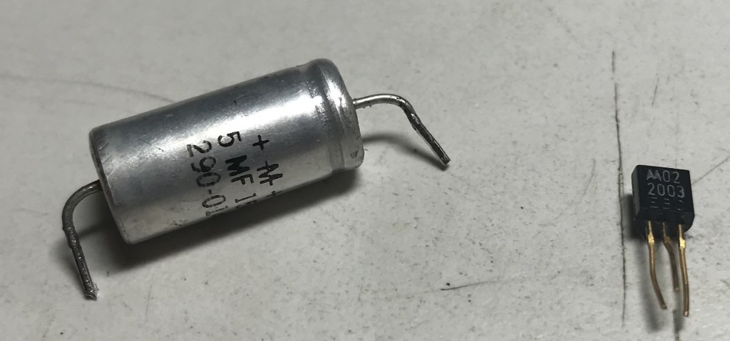
During this investigation I noticed an electrolytic capacitor that appeared to have some tarnish near one end. I decided to replace it before putting the scope back together. I looked up the value, and it was a 5 uF cap rated at 150 volts. I searched my stash and found I had nothing that would work in that application. I pulled the part and did some basic checks. It measured at 7uF. I found that resistance was infinity on my meter, although I know that means little. I have a primitive ESR checker, but it requires a working scope, so I couldn’t do that check. A search on Mouser showed that they had something in stock. However, the cost of two parts plus shipping was almost $15, so I decided that maybe the capacitor I had would do ok for now.

After replacing the capacitor, the scope refused to power up, with some apparent problem in the power supply. It made a ticking noise much like an Apple II power supply that doesn’t have a load. I double checked my soldering and could find no issue. At that point I decided to pull the cap again and order a new capacitor and do some research on the power supply before continuing…

Technology and the Civil War

The classic image of the Civil War portrayed by authors like Bruce Catton had men and horses marching on foot for days over dusty or muddy roads. This would be interrupted by an occasional horrible and not quite decisive battle. While this image of war is certainly true, there is another side to what was going on during the Civil War.

Troops were often transferred vast distances by rail or boat. Telegraphs were setup to provide almost instant communication across the same vast distances. Steam powered gunboats patrolled the rivers. Hospitals were supplied with running water. By the end of the war, economic warfare was a key part of the North’s strategy, while the southern forces embraced raiding and guerrilla warfare. Most northern cavalry units were equipped with breechloading rifles, many of them repeaters. Hydrogen balloons were used for observation, though later in the war it was determined that, if given a few days time, building a tall tower could achieve a similar result, with a lot less hassle and risk.

When I stopped at the National Archives late last year, I discovered that the men staffing the US Military Rail Road’s depot in Alexandria Virginia enjoyed some surprising luxuries. I found invoices for gas pipe and gas lanterns. Further research indicates that a gas works was installed in Alexandria in the 1850s. The USMRR railroad must have tapped into it.

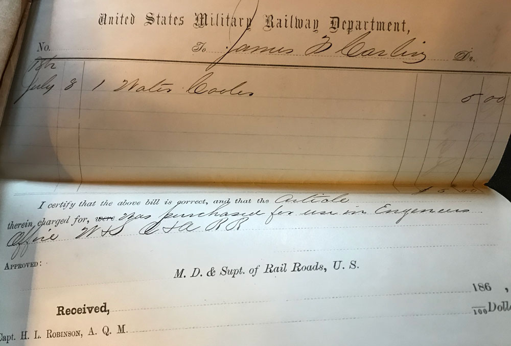
Invoice for Water Cooler

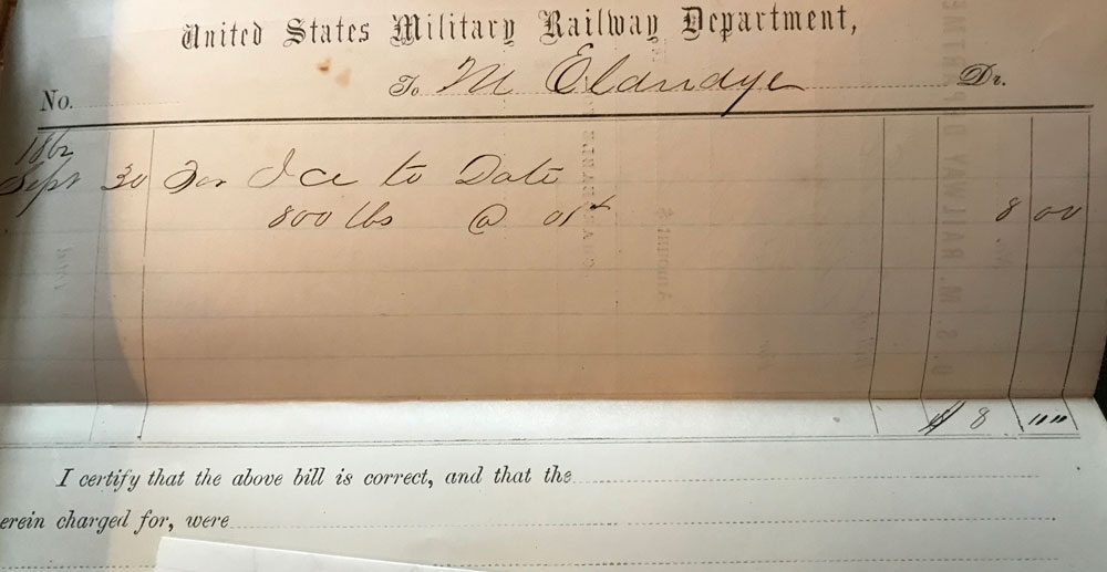
I also found invoices for water pipe, a water cooler and 800 pounds of ice. Finding the invoices for the ice and water cooler was quite a surprise.

Invoice for Ice
Invoice for Ice

Though those times were primitive by today’s standards, it’s clear that when possible, those soldiers would do what they could to make themselves as comfortable as possible.

Another Tektronix 465 Oscilloscope Repair

My faithful old Tektronix 465 has recently been experiencing issues with the delay function for the secondary horizontal timebase.

For those not familiar with this feature, here is a quick explanation: the Tek 465 has dual timebases. You can set up timebase A for say 1 millisecond per division and timebase B for say 10 microseconds per division and switch the horizontal timebase from A to B as the raster scans across the screen. This is useful when you want to zoom into the details of a signal sometime after triggering as the raster is partway across the screen. This switch in timebases can be by trigger or by a delay feature.

It’s basically a controllable zoom capability. I find the time delay version of this feature most useful, but recently I found that when the change in timebases was set to delay, it would trigger immediately, instead of delaying.

After several debug sessions, the feature started working intermittently. This slight improvement in behavior started after probing in the area of several suspect transistors. I pulled the most likely transistor out of it’s socket and tested it using a diode tester. It tested good. After reseating it and some other transistors, the feature seems to working reliably again, though only time will tell for sure.

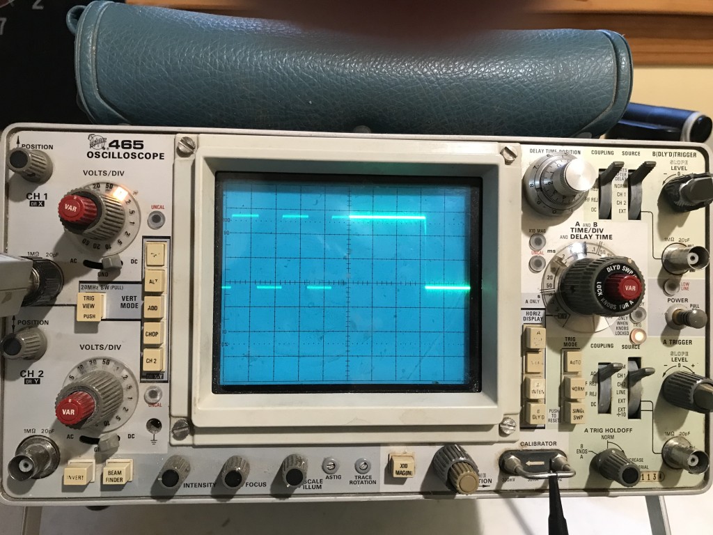
Dual Sweep Feature
In this demo, the trace of the 1KHz calibrator signal is set up to display at .5 ms per division until half way across the screen, when the timebase switches to 50 us per division. The slower rate of raster movement intensifies the display at the higher speed.

Anyway I took a good look at some relevant signals while it is working, so I’ll have a better shot at debugging it, if the problem crops up again.

There is nothing worse than intermittent sockets and connectors. I’ve had this scope for a long time and it has served me well, but maybe it’s starting to show it’s age a bit. By the way, as I don’t have a second scope, once again, I used this scope to debug it’s own issues.