SRT Meter Operation Notes
SRT meter adjustments
The SRT meter has two adjustable components. One is the electronic
circuit that controls the needle in the finder. The adjustment for the
electronic portion is easily reached by removing the bottom cover of the
camera. The other adjustment is the mechanical mechanism that controls
the circle in the finder. This adjustment is a bit harder to reach as
the top cover of the camera must be removed. I will describe here how the
electronic portion of the meter works.
Overall SRT meter electrical circuit diagram and operation
 Here is a diagram of the electronic meter circuit in the SRT 101.
The circuit is composed of only a few components. These few components
control the behavior of the needle in the viewfinder.
Here is a diagram of the electronic meter circuit in the SRT 101.
The circuit is composed of only a few components. These few components
control the behavior of the needle in the viewfinder.
- A couple of switches that disable the meter if the depth of
field preview is pressed AND the lens is stopped down below maximum aperture.
Note that one of the cameras I have, was built without the last switch adjusted,
so that as long as the depth of field preview is engaged, the meter would
be disabled, regardless of the f-stop setting on the lens.
- Two CDS cells that vary resistance depending upon the amount
of light hitting them.
- A variable resistor that is used to adjust meter sensitivity.
This is accessible by removing the bottom cover from the camera.
- Finally a meter that measures the current in the the circuit
and which controls in the pointer seen in the viewfinder.
- A battery that powers the circuit.
The circuit itself is essentially a current measurement system
that automatically adjusts the current depending upon the amount of light
falling on the CDS cells mounted in the viewfinder. A variable resistor
is used to fine tune this circuit. In order to fine tune the meter circuit
on the SRT, it is important to understand behavior in different lighting
conditions. Here is some actual measured data from a SRT's CDS
cells under different light conditions. Note how the CDS cell's resistance
and LUX intensities are essentially logarithmic functions.
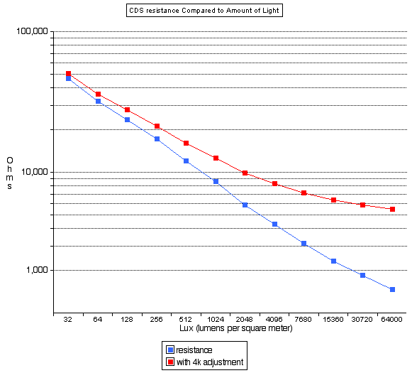
If the adjustable resistor was set to add 4k ohms resistance to the
circuit, the resulting plot is varies quite a bit from the basic measurement
in brighter light. This demonstrates that the variable resistor adjustment
has a much larger impact in brighter light than in dimmer light. This
is an important factor to consider when adjusting an SRT's meter.
Overall SRT meter mechanical diagram and operation
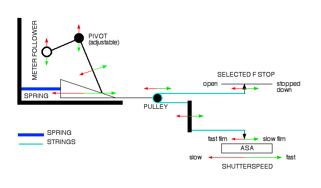 Here is a simplified not-to-scale diagram of the mechanical portion
of the SRT's meter. This system controls the behavior of the follower
needle in the viewfinder. This is the circle in the viewfinder that
moves when you change ASA, shutter speed or F-stop.
Here is a simplified not-to-scale diagram of the mechanical portion
of the SRT's meter. This system controls the behavior of the follower
needle in the viewfinder. This is the circle in the viewfinder that
moves when you change ASA, shutter speed or F-stop.
Basically, the follower is controlled by two strings connected by a pulley
mechanism and held under tension by a spring.
- One string is connected to the lens by means of the ring on the front
of the camera. This provides the system the selected F-stop.
- The other string is connected to the wheels that control shutter
speed and allows you to input your ASA setting into the meter.
The overall effect is that the follower needle goes down if you either,
decrease ASA, speed up the shutter or close down the selected F-stop on the
lens. The green arrows on this diagram show this effect.
The needle goes up if you either, increase ASA, slow down the shutter or
open up the selected F-stop on the lens. The red arrows on this diagram
show this effect.
There is also some adjustment built in, either by adjusting the strings
or the meter follower pivot.
In the actual mechanism, the strings are wound around wheels and are guided
through the camera by a number of pulleys. My reassembly page has
the Minolta factory drawings of the string configuration. The ramp
shown here is actually constructed as a spiral mounted on a wheel.
The spring that essentially holds everything together is a constructed
like a watches mainspring, so it fits convieniently under the wheels and
keeps the strings under tension. This is the same spring that holds
the aperature follower on the front of the camera over to the left (when
facing the front of the camera). By the way, without this tension the
strings will fall off the pulleys. There is even one pulley in the
camera that is held on it's post only by the tension of the string on it.
There is another smaller spring not shown on this diagram that keeps
the follower needle guide against the ramp, so it is sensitive to movement
in either direction.