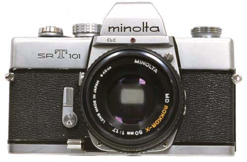
Mike's Minolta SRT Reassembly Page
Replacing the Front Base Frame (mirror box)
Follow directions in the SRT service manual. You might as
well replace the foam on the bottom of this unit while it is apart, if needed.
See the repairs section for more information.
- Make sure you slip the lever that protrudes out the top of the
mirror box down while you insert the mirror box into the body of the camera.
- If you have a self timer mechanism on your camera, remember to depress
the the self timer so it properly engages the shutter release rod. I
don't know how much time I spent trying to get the mirror box in, before
realizing the self timer must be manipulated to engage the slot in the shutter
release rod. Once you remember to do this, it is fairly easy to get
the mirror box in.
- I have used ordinary contact cement for reattaching the
leatherette. Just a very small amount will do, and I don't worry about
letting the glue set before joining the parts.
Replacing the Viewfinder
Before reassembly, you might as well check to see that the CDS cells are
firmly attached to the top of the viewfinder. If the CDS element moves
at all, the glue probably has failed and you must glue it back down. If
needed, you also might as well replace the foam on the viewfinder seats in
the body, unit while it is apart. See the repairs section for more
information about both of these items.
Follow directions in the SRT service manual.
- The wires that must be soldered were actually blue (towards
front of camera) and green (towards back of camera) on the cameras I have
seen.
- The black wire that must be soldered is soldered on the front
right hand (when viewing from the front) side of the camera.
- To replace the speed indicator string, you must wind up the spring
tensioned wheel four turns and then connect the tiny string. Start
with the speed setting set on the slowest speed, so that as little string
is free as possible. I use my finger to turn the wheel, a little at
a time. Then I hold the wheel in place with a bamboo skewer while I
reposition my finger to move the wheel further. Eventually I will have
wound the wheel four turns. I hold the wheel in place with the skewer
while hooking the string in the notch in the wheel. Trust me, this is
harder to do than it sounds. If you have a good method that works for
you, let me know about it.
Replacing the Lens Mount Assembly
I would replace the viewfinder first, as the aperture control string
rides on a pulley mounted on the viewfinder base.
- Make sure the aperture string rides properly on all pulleys as you
assemble the components.
- Lubrication is not needed on these components.
- If it binds or doesn't spring back smoothly when, either it is dirty
or something is bent. See repair section for possible remedy.
Replacing the AV Coupling String
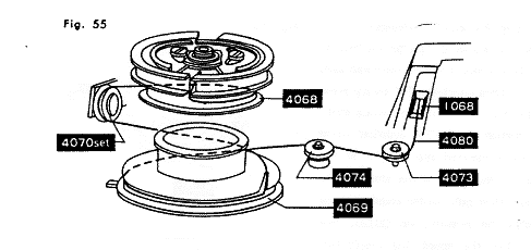
Here is a diagram from the SRT service manual that depicts the AV string
(the one that connects to the aperture mechanism). Replace this string,
before replacing the TV string. Here are a couple of things to keep
in mind.
- I have found it very difficult to get the string back on pulley 1068
without removing the the lens mount assembly.
- Pulley 4073 is not fastened onto the post in anyway other than
the tension of the string. If the camera is inverted without some
tension on the string, it will fall off.
- I found you should rotate the following needle assembly in order
to put some tension on the spring, prior to putting the strings in place.
- This string should be glued in the slot in wheel 4069.
- After replacing this string, for some reason I have found that the
switch that enables the meter in depth of field preview mode at minimum
aperture is usually out of adjustment. Why this happens is a mystery
to me, and I usually don't worry about fixing it.
Replacing the TV Coupling String

Here is a diagram from the SRT service manual that depicts the TV string
(the one that connects to the speed/ASA wheel). Replace this string,
after replacing the AV string. Here are a couple of things to keep
in mind.
- When both strings are in place properly, the spring in the following
needle assembly will be under some tension. This means there has to
be tension in the assembly when you put the strings in place.
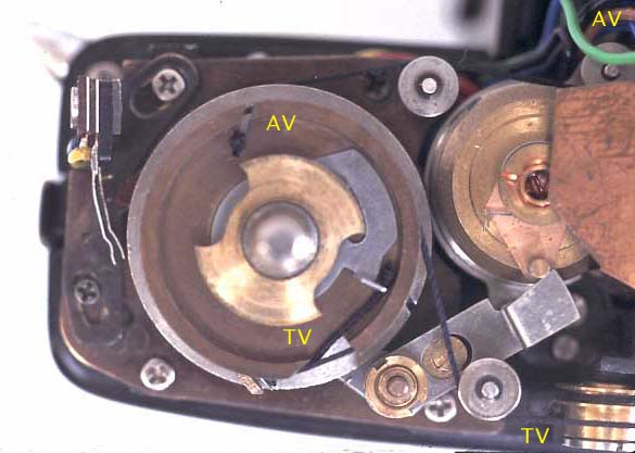
Top view of meter shows AV string coming in from lens mount and the TV string
from shutter control on other side of viewfinder. The TV
string just wraps around the topmost pulley a couple of times in a counter
clockwise direction.
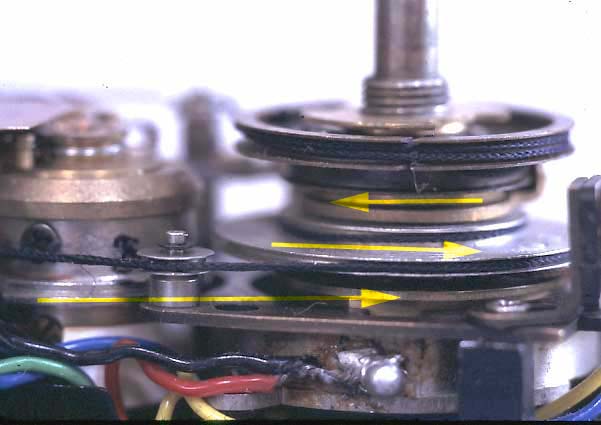
From the front of the camera, the stack of wheels that the strings are wound
up on. The yellow arrows show how the direction of the AV string
changes as it moves up the stack of pulleys.
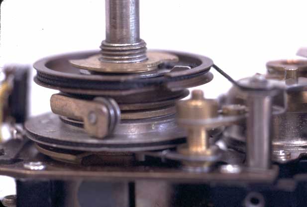
From the rear of the camera. This clearly shows the pully that reverses
the direction of the AV string.
Replacing the Top
Follow directions in the SRT service manual.
- Check that the viewfinder focuses properly, before putting the
top back on.
- Check that all strings are running on their pulleys correctly, before
putting the top back on.
- The speed control dial is easy to replace, once you get the hang
of it. The keys have two lengths, and have matching slots in the base.
Mount the dial as a unit with all components together, except
the screw. Once aligned and seated, rotate the dial clockwise until
the screw hole in the top becomes visible through the screw hole in the top
of the speed dial.
Replacing the Bottom
Follow directions in the SRT service manual.
- Nothing could be easier. Simply screw in the two screws
on the bottom plate with the appropriate screw driver.


