Automating and Maintaining Busch Crossing Signals
 Busch makes a nice set of crossing signals that include a blinker circuit
that sell for less than $30. I have installed a set on my layout and automated
them so that they blink whenever a train occupies the track near the crossing.
The total cost of installation can get pretty high, but I'm happy having
this bit of animation on my layout.
Busch makes a nice set of crossing signals that include a blinker circuit
that sell for less than $30. I have installed a set on my layout and automated
them so that they blink whenever a train occupies the track near the crossing.
The total cost of installation can get pretty high, but I'm happy having
this bit of animation on my layout.
Important Note: If you have multiple power boosters in your layout or
want to install multiple block detectors you should consult other sources
for your installation directions - these simple notes only apply to layouts
with a single power booster and a single set of signals to be installed.
To automating this crossing on my model railroad, I used the following
components
- 14VDC power supply. I used Radio Shack 12VDC- 500ma 273-1773. This
is really around 14 volts - about $10. I don't know the actual amount of
power used, but I would expect it is less than 100ma for the Block Detector
and the signals themselves.
- Circuitron Current Sense Track Detector BD-02 . You could build your
own current sensing block detector from instructions available on the internet,
but I purchased a BD-02 on sale for about $17. Since I only needed one
I decided not to build my own. Circuitron makes a heavy duty version, but
the standard version has plenty of power to run the Busch crossing signal
set.
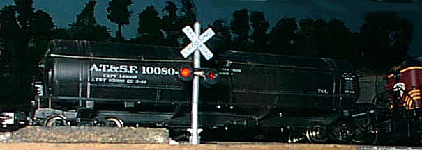
- Busch Crossing Signal Set - less than $30 Walthers part number 189-5934.
- Some 2 Conductor Wire - gauge not critical - connects DB-02 to signal.
- 2 - 5 amp rectifier diodes - Radio Shack part number 276-1661.
Layout Wiring
My layout was wired originally for DC, not DCC, so it has been previously
broken into blocks. One of the blocks already contained all of the track
on either side of the crossing to which I was adding the crossing signals.
 Installing rectifier diodes
The Circuitron block detector BD-02 uses diode dropping type current sensing.
This reduces voltage to the track by .6 volts. This will result in engines
slowing down when entering this block and speeding up when leaving it, unless
the voltage to the rest of track is adjusted. I added a pair of 5 amp rectifier
diodes into the circuit supplying all blocks, except the block connected to
the Block Detector. This will adjust the track voltage to an equal value
for all blocks once the block detector is installed.
Adjusting track voltage of your DCC system
My locomotives decoders were programmed for the old, higher track voltage.
The .6 volt drop was significant enough to affect low speed operation.
In order to make the trains run like they used to, I increased the power
of my Powerhouse Pro booster by .6 volts. Read the instructions that come
with your DCC system to see if you can adjust output voltage and how to do
it.
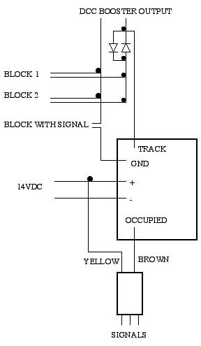
Connecting the block detector to the track
The BD-02 is connected inline to one of the wires powering the block that
is to be detected. One wire comes from the booster and connects to the
pin labeled TRACK on the BD-02. Another wire runs from the pin labeled
GND to the track. This circuit must bypass the rectifier diodes used
to match the voltage for the rest of the track. You should make sure that
the BD-02 is connected to the same output of the of the power booster as
the rectifier diodes installed for the rest of the track. Connecting to different
outputs could cause damage to your decoders or cause erratic operation. At
this point you should be able to operate you layout and see no difference
in speed or other problems when the train crosses from this block to adjacent
blocks.
Powering the block detector
Connect the DC power supply. I used a Radio Shack 12 DC 500 milliamp power
supply to operate the block detector. You don't need the plugs Radio Shack
provides, just cut off the adapter and strip the wires, then solder to the
appropriate posts. Use a multimeter to determine which lead is positive and
which is negative. Connect the plus to the pin labeled + on BD-02
and the minus wire to the pin labeled -.
Checking and adjusting the train detector
At this point you should be able to check functionality and adjust the
BD-02. This block detector works by measuring track current. This current
will most likely be created by one of three sources. A locomotive (current
is used to power the decoder, motor and lights), special wheel sets with
a resistor connected between metal wheels, and finally leakage of current
through the ballast or normal rolling stock wheels. The Circuitron block
occupancy detector has directions for adjusting the BD-02. Following those
directions should result in the occupied light on the detector is lit when
a train occupies the block surrounding the crossing.
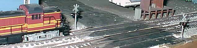
Installing the signals and tuning the flashing circuit
At this point you should have the block detection circuit working well
and only need to rig up the crossing signals. Installation can be a bit
difficult because of the small size of the wires connecting the flashing
electronics to the signals themselves. There are 3 wires running from each
signal to the electronics unit. You will most likely want to disconnect
the signals from the electronics unit in order to hide the wires and the
electronics unit under your layout. Before you do this, mark the wires
going to the center post of the electronics unit. You may also want to mark
the wires going to the left and right posts, but this is not required. Make
sure you mark the center wires in a very positive way. I found out the
hard way that confusing the wires can lead to destruction of some of the
electronics components. I used an indelible marker to paint the center wires
black.
To power the signals, you will have to connect the 2 wires running from
the electronics unit to the BD-02. The yellow wire goes to the + pin and
the brown wire to the OCCUPIED pin. In my case, I had to splice
in some extra wire to connect the two units since I have positioned the BD-02
near my power booster and the electronic unit must be located near the signals.
I would recommend testing the signals at this point before actual installation.
Before you actually install the signals, make sure that you have a comfortable
space under the layout to work and have positioned a light under the layout
so you can see well. Once you have the wires marked, you can pull out the
yellow plugs that hold the wires in place. Drill a small hole where you wish
the signals to be mounted just big enough to run the wires though. This
hole should be small enough that the base of signal covers the hole when
installed. Put the signals in place running the wires though the hole to
underneath the layout. I don't glue my signals down because they are located
near the edge of the layout and a stray hand or elbow would break them off,
if they were fastened down. Fasten the electronics unit underneath the layout
- I found that Atlas track nails fit nicely into the holes either side of
the unit. Make sure that the electronics unit is positioned such that the
wires from both signals will reach the mounting holes. Carefully run each
pair of wires to the appropriate mounting hole and insert the yellow plugs.
Because of the small size of the wires, I've found that having enough light
is critical to making this tricky job easier.
At this point, assuming that the wires are connected properly, you should
be all done and can now enjoy your new operational crossing signal.
Maintenance of the Busch crossing signal
During my first attempt at installation, I damaged the crossing signal.
I have found sources for some parts and learned how to repair this relatively
delicate crossing signal.
Disassemble signal
The signal is composed of three main parts glued together. The top of
the post, the arms supporting the signal lights and the bottom of the post.
The first signal I disassembled pretty much fell apart, with the LED's popping
out of the light fixtures with a little gentle pressure. The second signal
I disassembled, was glued together much better at the factory, and eventually
broke rather than came apart cleanly. If I was to try working on another
set, I would first see if a light pressure would separate the parts. If it
does come apart, you are ahead of the game. If it doesn't come apart, I
would try to pop the LED's out, without separating the plastic components.
You would have to feed the wires through the post very carefully at the
same time. In any case, I was able to repair the broken unit with a little
CA adhesive, when it was ready to go back together.
Replacements for burned out LED's
Minitronics sells an assortment of small LED's with resisters (part number189-5934).
The small red LED's will work as replacements for the Busch supplied LED's,
as long as you replace all 4 LED's on both signals together. The Minitronics
LED's require more power to operate, I think around 30 milliamps, compared
to about 20 milliamps on the stock Busch LED's (don't count on these measurements).
In any case the Busch circuit requires all LED's to be of the same power
to work properly. That is why all LED's must be replaced at once. The Minitronics
assortment supplies 470 ohm current limiting resistors with the LED's, the
same as the Busch electronics unit does. The Busch unit drives 2 LED's at
once through a single 470 ohm resistor, but that seems to work fine with
the replacement LED's.
Source for broken signal wires
Radio Shack sells a set of three sizes of magnet wire (part number 278-1345).
The smallest of these wires (30 gauge) is a match for the wire used by
the Busch signals in case you need to replace some wire. When I rebuilt
my signals, I used the original wire for the center lead and new Radio Shack
wire for the other two leads. Since these wires are different color, I was
easily able to keep the center wire separate from the outer wires during
installation.
Fixture for soldering the LED's back together
To make up the new led assembly for the signals, I took a piece of wood
and created a fixture by drilling two small holes that matched the LED lenses
in size, spaced the appropriate distance apart. I made sure the 2 LED's needed
to make a signal were connected properly before soldering together. I used
alligator clips and some scrap wire to connect everything together. Then
I connected a bench power supply adjusted to 14 volts to the electronics unit
to make sure everything worked. Once you have the unit connected correctly,
cut the leads on the LED's to an appropriate length. Place the LED's into
the fixture. Then carefully solder on the wires,
How the electronics unit works
I managed to destroy a transistor in the electronics unit and had to figure
out how it worked in order to repair it. The circuit basically uses a simple
RC network for timing and two transistors, one for each pair of LED's. While
switched off, the circuit will charge a capacitor through a resistor that
will eventually switch the transistor on and at the same time switch off the
other transistor. At this point the other half of circuit will start charging
it's capacitor until the process is repeated. The transisters can be replaced
with most any general purpose NPN switching transistor. Radio Shack part
number 276-2009 should work.
Speeding up the blink rate
My signals originally blinked at a rate of about once per second. This
is controlled by a RC timing circuit. The resister is 47 k ohms and the capacitor
is 4.7 uF. I noticed that the prototype signal down the road flashes at
a rate of about 2 times per second. In order to speed up the blink rate,
change the resistor to 22k ohms.