DCC Stuff
I recently bought a NCE Powerhouse Pro system and have been busy setting
it up as well as installing decoders in my small locomotive fleet. Here
is some of the things I have learned.
Athearn RDC installation - NCE D102EU
This install was my first and easiest, although I will tinker a bit more
with the lighting. Prior to adding a DCC decoder I had completed a couple
of modifications to the base Athearn RDC. I had added an Earnst regear kit
to this RDC. Also I had hard wired the top brush to the power pick ups.
Here are the steps I took to add a decoder to this unit.
The installation of an NCE D102EU into an Athearn RDC is pretty easy
- Remember that I protect all wire to wire connections from shorts by
covering with heat shrink tubing.
- Pop off the body and the motor.
- Apply a piece of black electrical tape on the chassis where the contact
on the bottom of the motor usually picks up power. This is fundamental
to all DCC installations. The motor must be electrically isolated from the
track.
- Use double sided tape to mount the decoder onto the chassis.
- Since I left the one side of track power pickup connected through to
the chassis, I drilled and tapped a hole for a 2-56 screw in the chassis.
- I used this screw to connect the trimmed red wire from the decoder
to that power pickup.
- I trimmed and soldered the black wire from the decoder to the other
side track power which was picked up off of the metal strip coming up from
the nearby truck.
- Remove the brush straps from the motor so you don't melt any components
on the motor when you solder the decoder connections on. Trim and solder
the gray and orange wires from the decoder to the straps that hold the motor
brushes in place.
- Since I don't have headlights on this model and this decoder has directional
lighting, I used the light outputs for interior lighting. Since lighting
is directional, I connected both white (front) and yellow (rear) light outputs
to one lead of a Minitronics 50 milliamp 12 volt lamp. I connected the other
lead to a 33 Ohm resistor to prevent the power on power surge from eventually
causing decoder failure and then on to the blue wire from the decoder. This
lighting system is just temporary, as I think a string of 2 or 3 lamps will
give more even lighting throughout this RDC.
I also had the starting from stop problem with this RDC as described in
the F7 decoder installation. I eventually solved the problem with this RDC.
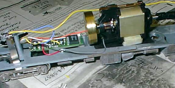
Athearn F7 installation - Lenz 103XF
I had a lot of trouble with my first Athearn F7 DCC installation blowing
up 2 decoders along the way. I am not sure even now what caused the decoders
to blow, but in both cases, I was fooling around trying to solve an operating
problem that occurred after the installation. Before I describe the installation,
I will elaborate on both of the problems.
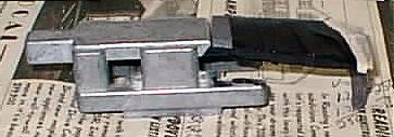
Athearn F7 with decoder installed, weight in rear
- The first problem manifested itself as a pronounced slowdown when making
a right hand turn when going forward, or left hand when going backward.
After much fooling around - and blowing a decoder, I discovered that the
wires soldered to the metal upright on the rear truck were rubbing on the
rear flywheel when turning right (going forward). I simply bent out the
wires to avoid this contact to fix the problem.
- The second problem was reluctance of the locomotive to start from a
standstill without a five fingered push, despite the fact that I could control
the lights. I tried cleaning the wheels and track, but this only helped
the problem a little. Being new to DCC, I was wondering whether the decoders
just didn't have the juice to kick start one of these engines. Along the
way, I blew another decoder. Finally, while experiencing the same problem
with my RDC, I tried cleaning the commutators on the motor. At last these
locomotives started working correctly.
Most Athearn owners have hardwired power pickups directly
Now the the high points of the decoder installation.
- Install two wires for decoder power from truck to truck. This is
the standard tune up technique for Athearn. Instead of connecting the leads
to the motor, use the leads only to connect the trucks together. Remember
that with DCC, the motor must be electrically isolated from the tracks.
I use a 100 watt soldering gun when soldering to anything like track, truck
or metal fitting. A lower power soldering iron takes too long to heat up
the metal, resulting in nearby plastic getting melted. When soldering any
delicate electronic component on a circuit board, do use a lower wattage soldering
iron. File any tarnish off the metal fittings, before soldering wire to
it. The solder will not stick very well if you don't.
- Add a piece of black electric tape in the well where the motor would
normally pick up power, in order to isolate it.
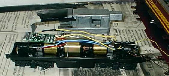
Side view showing decoder mounted to the rear of the motor and lead weight
above
- Deciding how to install the decoder into the F7 took quite a bit of
calculating. Most Athearn DCC installations in literature and on the web
apparently don't consider maintaining the super weight on the F7. It became
obvious rather early on that I couldn't maintain the weight as it came from
the factory. After much deliberation and calculating, I came up with this
modification. I mount the decoder on a chopped down piece of the metal strip
that was originally used for electrical pickup. This strip snaps on the top
of the motor and the decoder is attached to this strip behind the motor with
double sided foam tape. I reverse the weight with the protrusion facing forward.
I have previously replaced the Athearn "CAB" lighting with 60 millivolt 1.5
volt grain of wheat lights glued to holes drilled in the headlights, so the
protrusion doesn't interfere with any lights.
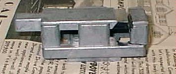
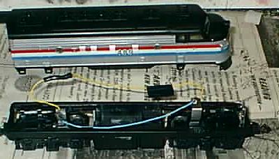
Weight showing piece to be removed already cut and how additional L weight
hangs on the rear
- I then cut the last upright off the super weight as shown in the photo.
Then I cut some sheet lead to form an L shape piece that will fit in the
rear end of the locomotive. The long part of the L is actually 4 thickness
of this sheet lead taped together with electrical tape for extra weight.
The top most piece of the sheet lead forms the little part of the L and
the lip that hangs on the modified super weight. I file a notch in the top
of the original weight for the sheet lead to rest on. If you don't file
this notch, the body will not fit all the way onto the chassis. Put electrical
tape anywhere you think a short to the decoder may occur.
- The rest of the installation is pretty straight forward. Connect
the track connections from the decoder to the each side's electrical pickup.
Motor connections are the same as shown in the RDC.
- Connect the forward light to the blue and white wire adding an appropriate
voltage dropping resistor. Test on the programming track.
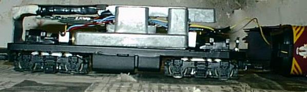
Proto 2000 SW9/1200 - Lenz 103XF
Although I initially had a lot of trouble with the Athearn F7 installation
described elsewhere, as far as space goes, this has been my most challenging
installation. This is another confirmation that I would be going nuts by
now, if I had chosen to model N scale. As you can see, I replaced the diode
lighting board with a Lenz 103XF decoder. There is very little room under
the hood in this model for extra wiring, resistors or anything else. You
could remove the weight and make things much simpler, but with my 3.5% grades,
I need all the weight I can get. Things are so tight that I actually had
second thoughts about taking the top off again in order to take this picture.
Here is a list of things I had to do, to fit this decoder.
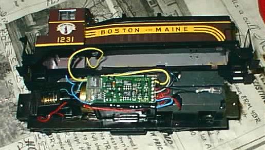
The SW 9/1200 decoder installation was a bit of a challenge
- The original diode circuit board was popped lose and the wires to
it were carefully desoldered. The mounting tabs for the circuit board were
cut off and top surfaces of the mount were filed to a level even with the
motor. The decoder was stuck on the top of the motor with double sided foam
tape.
- The left side power pickup wires from front and back were carefully
shortened so that they meet as close to the rear gear tower as was reasonable
to do. I left just enough extra wire to allow a second chance should I have
made some sort of mistake. The black power wire from the decoder was cut
to loop back and meet the pickup wires. Then heat shrink tubing was placed
over the wires and then the wires were soldered together. The same was
done on the other side of the decoder with the right side wires. You can
see how the red wires run in the gap under the edge of the decoder and the
top/side of the motor in the picture. The heat shrink tubing was carefully
shrunk around the wires with a lighter only after testing on the programming
track was complete.
- The bottom wire from the motor was shortened and spliced with the
gray motor wire from the decoder. The wires meet along the left side of
the motor. If I was to do this over, I would have soldered the motor wire
directly to the decoder as I did with the other motor wire. The orange motor
wire was desoldered the from the decoder before trimming and connecting the
other motor wire directly to this solder pad on the decoder.
- Before connecting the lights, I tested the basic decoder installation
in this chassis. I carefully covered the ends of the lighting leads from
the decoder with black electrical tape to prevent shorts while doing this
testing.
- As you can see in the picture, the headlight is disconnected from the
shell, and left to rest in the depression in the weight. One headlight lead
was also directly soldered to the decoder circuit board. That is, the white
headlight wire was desoldered from the decoder and then one lead from the
headlight was soldered directly to that pad on the decoder. The yellow taillight
wire was shortened and connected to one of the taillight leads. I left enough
spare wire to allow the body to be removed or attached, but not so much that
it would prevent mounting the body, altogether.
- The other light leads were each connected through a 150 ohm 1/4 watt
resistor to the blue wire from the decoder. This is the resistor specified
on Tony's Train Exchange web site. I think that perhaps 180 ohm or so might
work OK, and run a bit cooler, but I didn't want to repeat this installation
if the lights didn't turn out to bright enough. In any case, if you have
a melt down or have another problem such as a burned out bulb, don't blame
me. Do check out the section on this page that deals with dropping resistors
for more information.
- The resistors were wired such that the two resistors were connected
inline with each other. One end of the pair was connected to the taillight
lead and the other to the headlight lead. The blue wire from the decoder
was connected to the point in the center where two resistors were connected.
Heat shrink tubing was added before soldering. The end result is a slim
inline unit that can be squeezed in the gap between one edge of the decoder
and the motor. This unit can be seen in the picture just below the bottom
edge of the decoder.
Wires running to the rear of this locomotive must be kept to a minimum.
Although there are appears to be some room around the cab area/rear gear
tower, too much stuff in there will keep the rear truck from swiveling freely
or could rub on the rear flywheel.. My initial attempt at wiring the lights
resulted in this problem and I had to shorten some wires. You might try pushing
on the wires inside the rear of an assembled SW9/1200 with a long skinny
object by poking it through the gaps in bottom of the rear truck, if you
are having trouble.
Atlas RS3 - NCE DA102US
One thing to watch for is that many railroads ran RS3s long hood forward.
If that is the case for your road, the instructions below will result in
a backwards running loco. Switching the direction bit in CV29 will not move
the headlight to the other end. If you want to run long hood forward, you
will have to reverse the motor leads and the lights from front to rear. Reversing
the connections to the track pickups, will have no effect.
This has been my easiest installation so far. Follow directions exactly
as written on the NCE decoder instructions. The motor connections will be
on the opposite side from the original decoder board, but just run the wire
from the bottom brush between the decoder and the motor to the correct side.
Test for shorts between the motor connections and the power pickups with
an ohm meter before trying it out on the programming track. I tested my installation
and ran it before soldering the connections to make sure it was correctly
connected. After soldering on the wires, I used the original connector caps
to protect the connections from shorting against the weights at either end.
Also I trimmed the strap coming up from the bottom brush a bit, so it wouldn't
short against the decoder, which is mounted face down. The included bulbs
appear to be 30 or 40 milliamps, so I didn't bother using a dropping resistor
with this installation.
Decoder installations - Things to keep in mind
- Initially I had used the full length of wire as provided by the decoder
manufacturers. This is not a good idea. Long wires add to electrical losses
and increase the possibility of pinches, shorts, or rubbing.
- Use heat shrink tubing to protect your soldered wires from shorts.
Remember to put the tubing on the wire before you solder the connections.
I used a lighter to shrink this tubing in place. I was very careful to
prevent damage to the model while doing this.
- If your model slows down mysteriously when making left or right hand
turns, you should check to see if something attached to a truck may be rubbing
on a flywheel when it swivels.
- If your model sometimes will not start from a stop without a gentle
push, check for dirty track, wheels and commutators.
Calculating dropping resistor requirements - Bulb amperage
If you have a voltmeter and a variable DC power supply like I do, you can
easily calculate approximate bulb amperage and the size of dropping resistor
required for that bulb. What you do is connect an 100 ohm resistor to one
terminal of the power supply, one lead from the bulb to the other terminal
of the power supply. Now connect the remaining lead of the bulb to the remaining
lead of the resistor. Now slowly turn up the voltage on the power supply
until the bulb seems to be at the brightness that you want. If you know
the rated voltage of the bulb, check the voltage between each lead of the
bulb. You should be running at or less than rated voltage to ensure long bulb
life. Now measure voltage between each lead of the resistor.
Using Ohms law, you can compute amperage of the light bulb.
I = V/R (current in amps = volts divided by resistance)
Assuming 100 Ohms and say you see 10 Volts between the 2 leads of the
resistor.
I = 10/100 = .1 amps which is also known as 100 milliamps. (1000 milliamps
= 1 amp).
While you at it, measure the voltage between the leads on the bulb to
determine an approximate rating, if you don't know it already.
If the output from the decoder on your layout happens to be 14 volts and
you have 1.5 volt bulbs, you can now calculate the size of the dropping resistor
required for these bulbs.
Using Ohms law:
R=V/I (resistance = volts/current)
Subtract the bulb voltage from the output voltage of the decoder to determine
the voltage to use.
R=(14-1.5)/.1 = 125 ohms
In the case of the Proto 2000 SW9/1200 I used this method to help determine
the requirements of the dropping resistor.
I connected a 250 ohm resistor in the circuit with the bulb. I turned up
the power supply until the brightness was about what it should be. I measured
the output of the power supply at 19.56 volts and 18.35 volts across the resistor.
The bulb would then have the difference of these two measurements between
it's leads.
bulb voltage = 19.56-18.35 = 1.21 volts. Lifelike probably uses a 1.5 volt
bulb in this locomotive.
The current through the bulb is the same as that through the resistor
and can be determined by Ohms law.
I = V/R = 18.35/250 = .0734 amps which is about 75 milliamps
Finally to determine the dropping resistor required.
R = (14-1.5)/.075 = 12.5/.075 = 166 ohms which is a bit more than the 150
I've installed in my SW9/1200. Perhaps I would have been slightly better
off with the 180 ohm resistors I was thinking of using.
To determine wattage requirements multiply volts times current.
12.5 times .075 = .9375 watts. Those 1/4th watt resistors in my SW9/1200
are really not rated for the job they are doing, but I couldn't fit anything
larger. No wonder they run so hot! Perhaps I should think of another way
of doing this task.