256 Byte EPROM
Support For SCELBI-8H
The standard SCELBI-8H doesn't include any EPROM memory. This
makes booting the system fairly laborious. You must toggle in
a boot loader program using the front panel, in order to load any
significant applications. This issue was solved by SCELBI with
the development of a rather sophisticated monitor that was released
with the SCELBI-8B. That didn't help the original owners the
8H, but at least one owner, solved the problem by hacking an EPROM
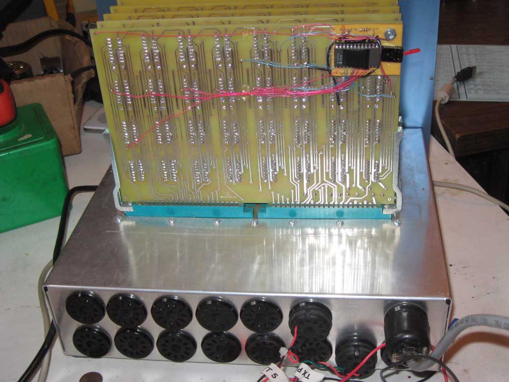
onto the back of one of his SRAM cards. Here is the back of
Steve Ciarcia's original 8H with switchable EPROM installed.
Once I took the time to develop a simple 8008 monitor that would fit
in 256 bytes, I had to add a 1702 EPROM to my SCELBI-8H. 8008
system owners should see my MCMON page
that describes the modified Creed Monitor that I adapted for the
purpose.
Steve's idea of adding an EPROM on the back of the last SRAM card
seemed to me to be the most logical solution to the problem.
The 1K SRAM cards used on the SCELBI-8H are quite easy to modify for
EPROM support. You add a daughter card that allows switching a
bank of memory between the new EPROM and the original SRAM. My
implementation puts the 256 byte EPROM at address 017-000. If
you need to use this address range for SRAM in an application, you
can always use the monitor to boot load a loader elsewhere in
SRAM. Then you can switch the EPROM range back to the SRAM
function. Here is how my implementation looks.
The wiring is pretty simple. You basically have to connect 8
data lines, 8 address lines, +5 volts, -9 volts and chip
select. Chip select for address range 017-000 needs to be
disconnected from all the pins on the chips that it connects
too. You can lift all the pins out of their sockets or just
cut the chip select line. I choose to cut the chip select
line. This line is then connected to the SPDT switch to switch
chip select of the last bank from EPROM to SRAM. When the
input is disconnected from the chips, you don't want the input
floating, so I pulled each input up to +5 volts with a 3K
resistor. The +5 and -9 volt lines are connected to a
convenient decoupling cap. The address and data lines are
connected to convenient vias. An alternative is to connect
address lines to the pins of an SRAM chip. I choose to use
vias because they are easier to solder to. Here is a diagram
of the wiring I ended up with.
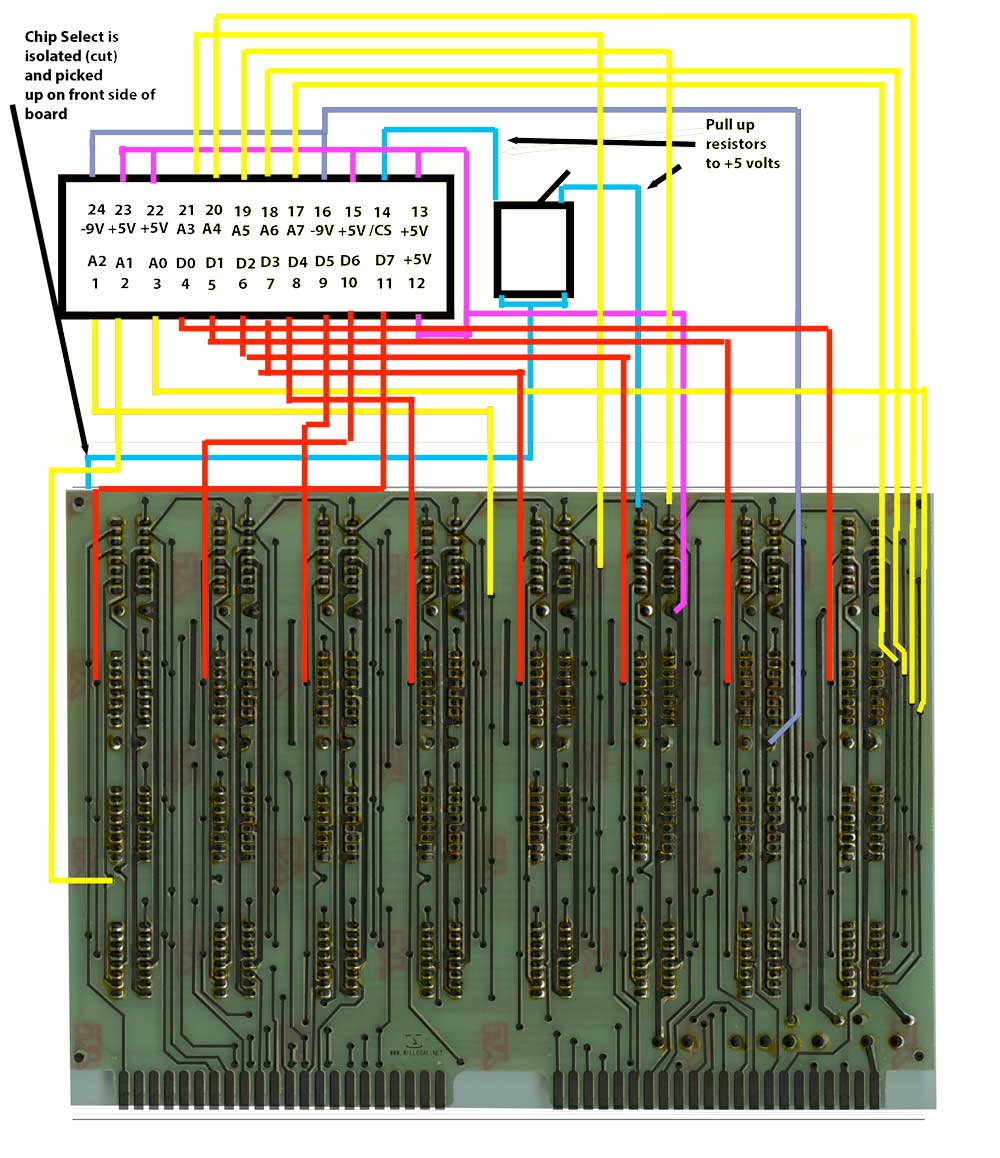
Red lines are the eight data bits. Yellow lines are the 8
address bits. Blue is chip select. Purple is +5 volts
and grey is -9 volts. The two pull up resistors are omitted,
but run from the two outputs of the switch to +5 volts.
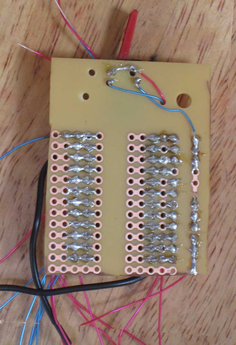
The EPROM is mounted on a section of a Radio Shack
proto-board. Since it only had copper pads on the
bottom, I completely wired it up before attaching it to the SRAM
card.
The daughter card is attached to the SRAM card with a #6 screw and
some washers to create clearance between the daughter card and the
main SRAM PCB. A thin piece of styrene plastic is also
inserted in the middle to eliminate any chance of shorts.