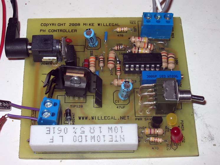
Update 6/12/2008 I finally built the PC board for this design. However it didn't work well. Switching was not positive and the controller could be put in a state where it rapidly cycled on and off. I have determined the cause to be a rather long trace connecting pin 10 input of the opamp to the connector which leads to the photo resistor. This input is sensitive enough that it will readily amplify any noise on this input. I will have to layout the board again with much shorter lead ins and see how that version works, before I publish the design. If you build one of these units be sure to check for positive on/off characteristics before you install it. An oscillating output could cause issues with overheating or at minimum wear out the solenoid prematurely. You may consider using shielded cable to connect the photo resistor with the board in order to reduce noise.
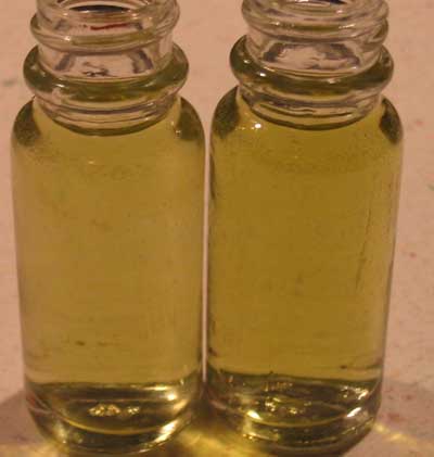
Update 3/26/2008 This design using a PH indicator solution for the probe is essentially bench tested and complete. I have even laid out a PCB for this design. Final step will involve actual connection to a CO2 system connected to a real aquarium. However reading some comments online about the extremely slow response time to PH chances for this design has made me think about a adding a front end that uses an "normal" PH probe. While the final "live" testing commences, I am investigating adding this second front end for a "normal" PH probe. While I'm at it, a back end for displaying actual PH might as well be considered. Stay tuned.
This
new version comes complete with an energy saving 12 volt, 1 AMP, solid
state, solenoid driver. As a
service to interested parties I'm posting some notes on current state
of that design, even though it has not been completely implemented and
tested. This design is based on a combination of my previous
design
(later on this web page) along with a solenoid controller design idea
that I found online at http://electronicdesign.com/Articles/Index.cfm?AD=1&ArticleID=11162.
I wouldn't use the solenoid controller design in
this article as is,
as it has some issues (read the article comments), but it did provide
the
foundation of the idea for my new design.
This article uses an
opamp to control current, so that the hold current can be lowered
shortly after the solenoid is switched on. This will save
significant energy,
which I think all of us should be striving to do. I have
adapted
the solenoid driver back-end to my existing PH sensor front-end.
The current with the 5 Watt solenoid that I am using, drops
from
over 500 milliamps during initial turn-on to around 100 milliamps while
holding in the on state. The design is
adjustible to a
wide range of characteristics by changing resistor values to suit your
particular situation. The controller consumes about 25
milliamps
when the solenoid is switched off and 121 milliamps when turned on
(after initial turn on surge). These measurements are with
indicator LEDs turned off.
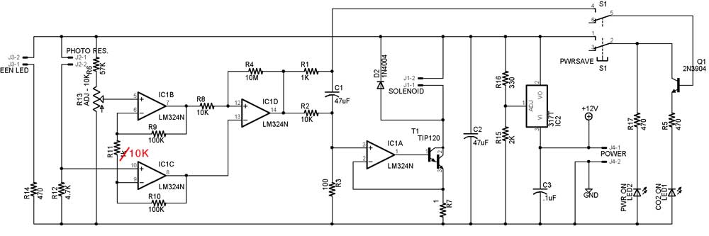
This design uses the same first stage amplifier (IC1B and IC1C) as my previous design. However since I needed an opamp to control power and I didn't want to add another part, I combined the final two stages of my previous design into one stage (IC1D). The last two stages on previous design were mostly redundant, so this change hasn't affected accuracy. R9, R10 and R11 are set up as a voltage divider and controls the amount of gain on the first stage of the amplifier. Increasing R11 will reduce sensitivity, since the difference between the negative inputs on opamps IC1C and IC1D will increase. R4 and R8 control hysterisis to opamp IC1D, which is set up as a comparator. This should prevent the opamp from flopping on and off rapidly.
The final opamp (IC1A) is used to control power to the solenoid through Darlington transistor (TIP120). Basically the negative input of the opamp is connected to the high side of a resistor (R7) which measures the current flowing through the transistor (and solenoid). This will cause the output to follow the input of the plus side input of the opamp. The plus input of the opamp is low when the solenoid is switched off and no current will flow. Note that depending upon the amount of current you end up sinking through the TIP120 in your application, it may require a heat sink.
When the comparator circuit detects the PH has risen, it will switch on and the plus input of IC1A will go to a level determined by the equation R3/(R2+R3) * supply voltage. In this circuit it will come out as 100/(10100)*12 or about .12 volts. This controls the on current of the solenoid. The opamp will automatically adjust output current so that voltage at the minus input is the same as the plus input. The current flowing through the Darlington transistor therefore will be this: .12 volts / resistor R2 (1 ohm) which equals 120 milliamps with these component values. Steady state on current can be adjusted by tweaking the R2/R3 relationship.
However during initial switch on - additional current is temporarily added to the plus input of the opamp IC1A while capacitor C1 is being charged. This will cause the voltage at the plus input to be raised. The opamp will automatically adjust output so that negative input matches the positive. This will allow additional current to flow through the solenoid during the turn on phase. The length of time of this addition current is determined by the size of capacitor C1. Increasing the capacitor's value will lengthen the period of extra current. Lowering the value will reduce the period. The size of the spike can be adjusted by adjusting the ratio of R3 to R1. Increasing R1 will reduce the spike as C1 will charge more slowly and reducing R1 will increase amplitude of turn on spike as C1 will charge faster.
With the values in this schematic, the spike reaches a little over 1 volt and lasts about a quarter second or so. One volt equals 1 AMP through the transistor, so this should be plenty big enough for most any suitable solenoid. Note that actual current will probably be less, depending upon the solenoid you choose. Divide the voltage across the coil (12V) by the measured solenoid coil resistance to determine actual worst case current through the transistor.
Also make sure that you use a 1 ohm resistor (R7) that is rated for the wattage that it will see (watts = volts * current). With my circuit - 1 volt (initial turn on voltage) times 1 amp (max current at turn on) = 1 watt. So at least a 1 watt resistor is needed.
The switch on the upper right controls power to two LEDs. One indicates that the controller is powered up and the other indicates whether the PH controller has enaged the solenoid or not (on means engaged). In the interest of energy conservation power to these two LEDs can be switched totally off with the switch. I will probably ground the other inputs to the switch to ensure stable operation of the circuit.
The voltage regulator LM317T, smooths out a 60HZ ripple that was passed on by the inexpensive 1 AMP DC wall wart power supply that I was using. During initial testing without the regulator, there was a noticable 60HZ humm eminating from the solenoid. Adding the regulator also introduces the possibility of easily tweaking power to this circuit. R15 and R16 are used to set the voltage. Increasing R16 reduces voltage. Reducing R16 increases voltage. The opposite is true of R15. With the values shown on the schematic I'm getting a supply voltage of about 11.31 volts. The LM317T is good to above 1 AMPs, but may need a heat sink depending upon the amunt of current that needs to be provided.
| Resistors | |
| R1 | 1K |
| R2 | 10K |
| R3 | 100 |
| R4 | 10M |
| R5 | 470 |
| R6 | 57K |
| R7 | 1 |
| R8 | 10K |
| R9 | 100k |
| R10 | 100K |
| R11 | 10K |
| R12 | 4.7K |
| R13 | 0-10K Trim Pot |
| R14 | 470 |
| R15 | 2K |
| R16 | 330 |
| R17 | 470 |
| Caps | |
| C1 | 47uF |
| C2 | 47uF |
| C3 | .1uF |
| Transistors | |
| T1 | TIP120 |
| Q1 | 2N3904 |
| LEDs | |
| LED1 | red |
| LED2 | green |
| ICs | |
| op-amp | LM324 |
| Diode | |
| D2 | 1n4004 |
| Switch | |
| S1 | DPDT |
| Jacks | |
| J1 | solenoid |
| J2 | photo resistor |
| J3 | green LED |
| J4 | power |
Back to Mike's Hobby Home Page