Beginning of Year Retro Update

Mimeo’s

Last weekend, I sold the last of the Mimeo PCBs (Glossy and Matte) that I had in stock. I will make some more matte after I’ve sold some of the first batch of the SCELBIs. I’m down to 4 ACI cards, so I’ll have to do a batch in matte to go with the next batch of Mimeos.

The new movie, “jOBS” will premiere at the Sundance Film festival this month. I’m hoping that the Mimeo PCBs that I sold to the prop house supporting the film, get some screen time and the film is good enough to get some decent reviews.

I still have plans to do a full built up system, but that project will have to wait until I have the SCELBI going. I am sorry that this has been teaser for some folks who have been waiting for it. However, I’m hoping that when I finally get to it, that folks will be impressed with the results, and say that the wait was worth it.

The new run of Datanetics PCBs have been trickling out, maybe a little faster than I expected, given the difficulty of finding components. They have mostly been combined with Mimeo PCB sales. I really wonder how many will get built up. This datanetics PCB batch has been done more of a service to the retro community, as it will be a while before this project breaks even financially.

SCELBI

Quotes from Advanced Circuits on SCELBI boards are about half of what I expected, which is awesome. Nashua Circuits came in as expected, so I guess Advanced will get this business, unless Nashua can do much better (I’ll give them a chance to improve their quotes). Since there is no solder mask, it really shouldn’t make much of a difference who makes them.

Design checks on the base 5 board set is done, and I’m about ready to declare victory on the layout tweaking/matching. The 8H backplane is just about ready, so I’ll probably get a batch of those made to go with the base 5 board 8H set, making it a 6 board set. The backplane has been challenging, as there is no schematic, only a wire list intended for wiring your own chassis. Good images of the top of backplane are non-existant. My orders for the PCBs may go in, as early as this week.

I do have one thing to check on the CPU board. There were at least two versions of the CPU board made, I am replicating a later version. There is a report of an issue with the step function reported SCELBI digest, issue II. Though describing a problem in a later version of the CPU board, this report shows a slightly different design than the one in the version of the schematics/layout that I am replicating. I just need to make sure the schematics that I’ve followed are accurate.

At this writing, estimates for the set of 6 PCBs, with an 8008D thrown in, but no other components, is in the range of 300 dollars. Final price might vary a bit, but I doubt that I could make it go any lower, without making this a one off effort, not to be repeated.

A friend of mine, is looking into doing a reproduction bezel for the front panel of the chassis. He tells me that there are some challenges, as the original was anodized, and most panel manufacturers, these days, do powder coating.

Today, I am going to see if I can generate a BOM (bill of materials) in an excell spreadsheet. Except for the 8008 and memory, I think most of the rest of the electronics components are readily available. I plan on sending the BOM to Unicorn, who have indicated, a while back, that they would do parts kits for this project, like they have for the Mimeo/Apple 1. The relay sockets used for I/O ports in the chassis, are available, but expensive – I’m going to see if I can find a way to get bulk price on those from someone.

The 8B will follow on the heals of the 8H, It uses the same front panel, CPU, DBB, and input boards as the 8H, but requires 4 new boards…

  • new backplane with an extra slot for the memory addressing board. I haven’t investigated in detail, but I hope I can leverage most of the 8H backplane design, making this pretty straightforward
  • new 4K memory module. I already have done the base chip placement for this one
  • PROM board. Cameron Cooper has a draft design, that he says he will let me leverage
  • memory address expansion card – haven’t started
  • All in all, you can see that based on the head start that I have on the 8B boards, this shouldn’t take nearly as long as the 8H has taken, to complete.

    After these are done, there is more SCELBI hardware to be done, a TTY interface, a scope interface and a cassette interface. Power supplies are another potential future project. For now you will need to find a 5 volt and -9 volt supplies. Amperage ratings depend upon the amount of memory and peripherals. According to SCELBI documentation, system with a keyboard, oscilloscope interface, and cassette interface requires the following.

  • 4K memory requires 5 volts at 6 AMPs and -9 volts at 3 AMPs
  • 1K memory requires 5 volts at 3 AMPs and -9 volts at 1 AMP
  • I’m also likely to do an automated front panel controller with a micro-controller, to make loading the memory on the 8H easier. I might be able to reuse my existing PS/2 adapter with a new program in order to accomplish this.

    Brain Board

    Brain Board stock is dwindling, but sales have been very slow, as of late. When the stock runs out, I’ll definitely hold off on making a new run, until demand builds up again.

    SUPERPROTO

    So far, interest has been a bit lighter than expected. However I’ve got wind of a couple of super cool SUPERPROTO based projects, that may just jumpstart sales when the projects are publicly announced. Feedback from folks using the card has been positive, with no unexpected problems or issues reported. I also know of one, well known, Apple II hardware designer that is leveraging parts of the design, which I have published in detail on the SUPERPROTO Wiki, for his next efforts. Even though, I get no financial reward from this leveraging, it is gratifying to know that my efforts are of use to others.

    Apple II rev 0

    A rerun of these PCBs is also in the cards, though I want to make a few tweaks, so it will also come after the SCELBI and probably the fully built Mimeo.

    That is all the retro stuff that I can think of, for now – Happy New Year

    Interesting Brain Board remote switch

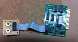
    Corey Cohen came up with this easy method of creating a remote switch panel for the Brain Board. Here is an image of his prototype version. Knowing Corey, I’m sure that his final version will be mounted on a nice plexi panel.

    Brain Board Remote Switch Thingy

    Brain Board Remote Switch Thingy

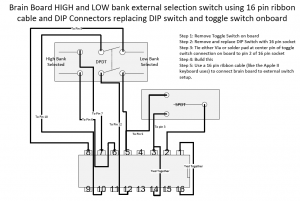
    One DPDT switch controls which bank on the brain board is selected. Corey has loaded integer basic and the original monitor onto his second bank. The other SPST switch controls whether brain board or motherboard roms are selected after reset – this second switch is essentially the same as the firmware board toggle switch.

    One wire needs to be added to the back of brain board to connect Apples reset to the DIP socket at pin 2. Reset can be picked up from the onboard switch location. It is the center of the three holes.

    A ribbon cable is used to connect the remote switch box to the Brain Board. As you long as you stay within reason, longer ribbon cables than pictured should pose no issues. The only active signal is reset, which, when asserted, is held low for relatively long periods of time.

    Brain Board Remote Switch Setup

    Brain Board Remote Switch Setup

    Wozanium fix for new Apple 1 Program/Hack

    It’s been a while since I found an Apple 1 program that didn’t run on the Brain Board/Wozanium, but there is a new program out for the Apple 1 that uses the ACI for audio out.

    http://www.applefritter.com/content/8k-apple-i-ascii-graphics-lunar-lander-aci-audio-hack-0

    Copied here, is my post on the Applefritter forum, describing the fix.

    This program will not work as is, with versions Brain Board/Wozanium pack firmware less than version 5.2. There is an issue with the the gosubs 750s in the 900 range (at the end of the program). Those gosubs call directly into the original Cassette interface driver to generate sound. This driver is still present in the Wozanium PROM, but is incompatible with Apple II hardware and will crash the system.

    There are several fixes available.

    1) remove the call 750s at the end of the program. LInes 900 and 910.

    2) Change the pokes in line 999 to call the Wozanium A2 cassette Driver at 0xd0d7:
    999 POKE 750,169:POKE 752,32:POKE 753,215:POKE 754,208:POKE 755,96:RETURN

    3) If you have a PROM burner, fix the Wozanium cassette driver to work with the A2 hardware by erasing a bit in the PROM – change location 0x01EA in PROM from 0xBC to 0xAC.

    4) If you don’t have a PROM burner, send your board or prom back to me and I’ll erase the bit for you.

    With fixes 2, 3 or 4 in place, you can attach a preamp to the cassette output of the Apple 2 and get the same sounds as if you were running on an actual Apple 1. It’s kind of funky because the A2 has a built in speaker, which is bypassed, but it works.

    If you are running a Wozanium PROM image in an Apple II emulator either:
    1) remove the call 750s at the end of the program. Lines 900 and 910.

    2) change line 999 to call the Wozanium ACI driver at 0xd1d7:
    999 POKE 750,169:POKE 752,32:POKE 753,215:POKE 754,209:POKE 755,96:RETURN

    Finally if you don’t have a preamp for the cassette output, there is an inexpensive design on my website that will work for this application.
    http://www.willegal.net/preamp/preamp.htm

    “Retro 1” Systems

    Marty Ewer is now selling “Retro 1” systems on ebay for $249. They are fully tested Apple IIe computers equiped with my Brain Board. If you are looking for the easiest, least expensive way to an authentic Apple 1 experience, this may be it. In addition, you get a working Apple IIe in the bargain. Search for “Retro 1” under user “shockwavetechnologies” on ebay.

    http://www.ebay.com/sch/shockwavetechnologies/m.html?_nkw=%22Retro+1%22&_sacat=0&_odkw=retro+1&_osacat=0&_trksid=p3911.c0.m270.l1313

    Brain Board 74LS244 Grounding Issue

    The Brain Board review in Juiced GS included a description of a bad 74LS244. I have had one other report of problems with the Brain Board in an Apple IIe. In that second case, I had that person send back his board, twice. Though I wasn’t able to reproduce the problem in my Apple IIe with his board, I tried two different repairs, the second of which seems to be successful. The first was a simple swap of the 74LS244, which helped, but didn’t completely eliminate the problem.

    After further analysis, I determined that the grounding of the 74LS244 is less than optimal on the Brain Board and switching on of the 74LS244 causes a lot of noise on the ground. Apple boards that use a similar data bus driver circuit (Apple FW card & Super Serial) also exhibit this switching noise. The stock Brain Board is somewhat worse in this regard. I found that adding an additional ground wire on the 74LS244 reduces noise to levels lower than the Apple FW board and appears to solve the problem.

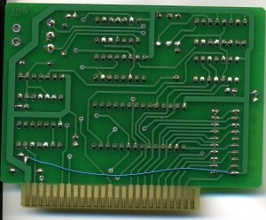
    This intermittent operation is typically seen as random characters input while at the console prompt, while not actually typing on the keyboard. If you notice this problem, add a wire between the ground pin of the 74LS244 and the ground lead of the decoupling cap near the other end of the edge connector.

    Here is an image of a board with the fix applied.

    brainboard 74LS244 ground wire fix

    brainboard 74LS244 ground wire fix

    One more word about this problem. Though I didn’t know of any issue with the ground, when laying out the production Brain Board, I considered shortening the ground connection to the 74LS244, running it across the center of the board, instead of the top. This change might have prevented this issue. However, I decided that, since, in several years of operation of the prototype “Brain Board”, I had seen no issues, that it was unnecessary. This is a case where the “if it ain’t broke, don’t fix it” approach, was the wrong approach. For now, the one wire fix will have to do. If I make another run of these boards, the ground trace will be widened and rerouted using the shortened path I considered before.

    Also because of this issue, I’m going to have to make major changes to the layout of the protoboard that I have described earlier in this blog.

    Wozanium Pack Source Code and Rom File Suitable for A2 Emulators Released

    Ken Gagne was kind enough to take some Brain Boards out to K-fest and sold them at the vendor fair. Do to these extra K-Fest sales, I’ve now managed to cover my costs in producing the “Brain Board”. Thanks to everyone that has purchased one (or more) of these units.

    Because I’ve covered my cost, and it might be interesting to some folks, I’m now releasing the source code for the Wozanium pack.

    Also included, is a ROM file suitable for emulators, such as Virtual II. This allows you to run and debug Apple 1 software in the Apple II emulator environment. Just select the .ROM file as the ROM for your machine and reset your virtual machine. Just as in the Brain Board, right arrow will clear the screen. With Virtual II, you can download AIF files of A1 basic and assembly language programs and run them in your emulated Apple II, using the emulated cassette interface built into Virtual II. Note that this ROM version does not include the ACI driver at C100, so you must enter the Cassette driver by entering “D000R”, instead.

    You can build the source with the 6502 DASM cross assembler.
    Use the following command line:
    “dasm a2a1emulv5_1.asm -DBLD4ROMBD=0 -DHUSTNBASIC=0 -oa2a1rbh.o -la2a1rbh.lst”

    Included in this zip is

    * a1basic-universal.asm – Apple 1 BASIC modified to run on Brainboard/Wozanium (note copyright at beginning of this file)
    * COPYING.txt – GNU lincense for rest of Wozanium pack
    * a2a1emulv5_1.asm – Wozanium source code
    * a2a1emulv5_1.lst – Listing
    * a2a1emulv5_1.o – Object file
    * a2a1emulv5_1.rom – 12K rom file that can be used with A2 emulators, such as Virtual II.

    Click a2a1emulv5_1.zip to download Version 5.1.

    More about the Brain Board can be found at:
    http://www.willegal.net/appleii/brainboard.htm

    Which Apple Interpreted Basic is the Fastest?

    While at the vintage computer festival, I had an Apple 1, an Apple II with integer BASIC and an Apple IIplus with Applesoft all up and running.

    At one point late in the afternoon on Sunday, I decided to have a simple performance contest between these machines. This is the program.

    10 FOR I = 0 TO 10000
    20 NEXT I
    30 PRINT “DONE”
    40 END

    Two machines were matched against each other and the program started at the same time on both machines. The first to finish was the winner.

    After several heats, here are the results.

    1st place – Apple 1 – by a little
    2nd place- Apple II
    3rd place – Apple II plus – way behind

    At first, I was confused by the Apple 1 beating the Apple II, as the Apple II should run about 5% faster than an Apple 1. This is do to the more efficient method for refreshing memory on the Apple II. The Apple 1 stops processor clocks while refreshing, while the Apple II uses unused portions of the 6502 bus cycles to refresh memory (and read video display data). Integer BASIC on the Apple II is a direct development of Apple 1 Basic, so I was thinking that the performance would depend on the processor, not the Integer BASIC implementation, which were basically the same.

    After a while I realized that Apple 1 BASIC might be a little simpler than Apple II BASIC and thus faster. I ran a second test. In this test, I booted the A2plus that I had there at the show into Apple 1 mode, with the Brain Board/WOZANIUM and ran the test against the original Apple 1. Both machines were now running virtually the same version of BASIC. In this case, the Apple II beat the Apple 1 by the expected amount. Thus, Apple 1 BASIC running on an Apple II, is the fastest version of Apple BASIC.

    However, keep in mind that if print statements are added to the loop, the Apple II will beat the Apple 1 by a substantial amount.

    Note on BB assembly, Version 5.1 PROMs shipped, and Why Is the BB Upside Down?

    For people that still had the FCS, 4.0 PROMs, version 5.1 PROMs were shipped on Monday and should be in your mailboxes soon. I will only be updating version 5.0 PROMs upon request. The only difference between version 5.1 PROMs and 5.0 PROMs, is in the power up screen and it doesn’t affect operation in any way.

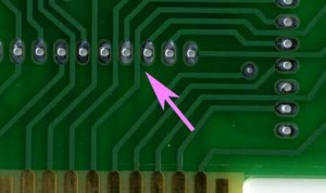
    Though assembly is really straight forward, there is one thing to watch out for when assembling Brain Boards. Where the traces run between pads, the soldermask reveal extends right up to the edges of the traces and, on some boards, where registration isn’t perfect, the solder mask reveal may expose a tiny part of the trace. There is potential here for shorting the trace to the pad when soldering a component to this pad.

    Brainboard-soldermask

    When soldering these pads, be careful that you don’t accidentally bridge the gap between the pads and the adjacent trace. If you can’t get rid of the bridge with a solder wick or solder sucker, the easy fix is to cut the solder bridge with a hobby knife. Check continuity with an ohm meter to make sure the connection is broken.

    Is the Brain Board Designed Upside Down?

    It’s funny that no one has questioned or commented about the upside down layout on the brain board. This was done on purpose because of the vastly improved layout possible with upside down chips. The layout of the address and data bus connections between the 27c256 and 74LS244 sockets and the edge connector would be much more complicated if the chips were right side up. Flipping the 27c256 right side up moves the data bus connections of the 27c256 to the opposite side of the chip from the 74LS244 and Apple data bus. Also, all the lower address lines would have to be crossed to properly connect the 27C256 to the Apple bus.

    Once I flipped the 27C256, I figured I had to flip all the chips and the silk screen to prevent confusion and mistakes during assembly.