SCELBI Backwards Capacitor Update

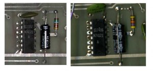
Take a look at these two images of original SCELBI boards.

Backwards Capacitor

Backwards Capacitor

The second one has the plus sign manually removed and the capacitor reversed. I did a quick test in my “lab” and found that indeed the “negative” side is about 1 volt higher in value than the “plus” side. Those capactors definitely should be reversed. While you are at it, make it authentic and manually remove the “plus” sign.

SCELBI Cassette Write Board Build Instructions

I’ve been working on writing detailed build instructions for the SCELBI Cassette Boards. I need to do this, because I haven’t found original build instructions. There have been a few challenges with the cassette boards, as the schematics haven’t always matched existing boards. Also, the initial version of schematics I had, were missing some labeling information on resistors and capacitors. I recently obtained images of some later schematics and got to examine a original board that help fill in some of those gaps.

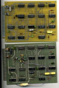
My reproduction was built to match the earlier schematics and a couple of different boards that I had images of. As part of this documentation process I had a chance to compare an original board with my reproduction. Here is a side by side scan of my reproduction next to that original SCELBI write board.

Original and Reproduction Write Card Comparision

Original and Reproduction Write Card Comparision

You can ignore the circuit in the relay socket. That was put there for debugging purposes, way back in the 70’s. It was basically using LEDs to indicate when the RELAY circuit was activated. The different color substrate is due to evolution of technology. The old green substrate is no longer made, because it fluoresces which affects modern photo based PCB fabrication processes. Some reproduction guys are dying their modern boards to give their reproductions the old time look.

Going through the later schematics and this board revealed a few things.

  • one of the electrolytic capacitors is reversed. I need to take a closer look at that before something bad happens. This is a serious issue as inserting electrolytic capacitors backwards can cause them to catch on fire.
  • This card has plain 7493s installed and seem to work fine. Clearly, the problem I experienced with this part in location Z4 is a marginal issue, and in some cases 7493s may work there with no problems.
  • This board uses (and the schematics have at this location) a .33uF film capacitor, though putting a .47uF capacitor here will have no effect on performance or behavior.
  • The 74121 timing circuit uses a 47K resistor instead of 56K. This is reflected in the later version of the schematics that I have. I’ll have to try the 47K resistor in my circuit to make sure everything is OK with that setup.
  • Finally, I noticed that I accidentally put a 1K pull up resistor in a location that calls for a 10K resistor (R5) in my reproduction. This should have no affect on performance, but I plan on fixing this mistake.
  • Here is my current version of the cassette write board build instructions.

    8B- Cassette Write board – build instructions

    I tried to make them match the style of original SCELBI build documents. Note that I need to investigate a few more things including that reversed 10uF capacitor before finalizing this document.

    SCELBI Cassette Chassis Artwork and Front Panel Screen

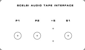
    Here is the artwork I’m preparing for the front of the reproduction SCELBI cassette chassis.

    Artwork Front Cassette Chassis

    Artwork Front Cassette Chassis

    Dimensions are 6″ x 3.5″. I’ll either directly silk screen the chassis or make decals. The crosses are drill points for binding posts and Amphenol connectors. I believe the holes for the binding posts will be 1/2″. The Amphenol connectors also get 1/2″ pilot holes, and then will be punched out with a Greenlee chassis punch.

    I tried doing a direct transfer from a laser printer printout, but I’m not satisfied with the result. This is essentially the same process as the laser printer PCB etch method. You print onto glossy paper then apply the image by melting the toner onto the target material. The problem is that with a PCB, you can roughen the surface with sand paper to get the toner to stick. I’m not interested in damaging the surface of the chassis and the surface of the chassis is too slick to make it stick consistantly.

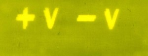
    I’m doing a fourth round on the front panel silk screen. The third round failed when I messed up registration of the two layers of transparencies that I used as a mask. I use two layers to ensure a good image. This time, I didn’t have them lined up exactly and I ended up with a nice screen, with a double image towards one end. The good news is that I think I have solved the other problems that I have been dealing with.

    Bad Screen

    Bad Screen

    SCELBI 8B front panels status

    Now that I have basic tape support going on the OS/X emulator app, I’ll get back to work on screen printing the front panels. My first two attempts to make a screen failed. On the first one, I didn’t get the screen stretched tight enough. The second attempt failed when I couldn’t rinse out the emulsion – I had probably left it dry too long. Hopefully third time is a charm.

    SCELBI OS/X Application Status

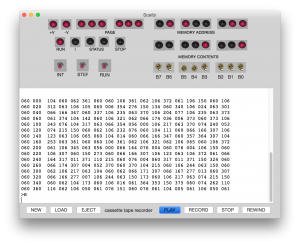
    My OS/X Macintosh emulator now supports reading and writing SCELBI compatible AIFF audio files, but I have to do some major work on the associated TTY terminal emulator window, so that I can successfully run the MEA editor in emulation.

    A while back, I had introduced 8008 cycle counting and timing on the OS/X version of the emulator, so that I could support SCELBI front panel operations and run it at prototypical speed. This made implementation of the tape read fairly straight forward in that environment. I recently added a configurable memory menu option to switch between an 8H and an 8B configuration and have a built in MEA PROM image that can be enabled, as well.

    SCELBI OS/X Emulator Reading a "tape"

    SCELBI OS/X Emulator Reading a “tape”

    Once I clean up the emulated tape interface a little, I’ll make a new version available for download. The editor part of MEA will still have problems until I fix the TTY terminal behavior, but there are a lot of other improvements in this version that may interest people.

    Once I get the TTY emulation fixed, the OS/X emulator will have practically all the functionality of a real SCELBI 8B or 8H with TTY and audio tape interfaces.

    I’ll look into what it would take to add it to Apple’s app store. I also might work on converting it into a IOS app for iPhone or iPad at some point. I did some experiments with IOS a while back and had basic 8008 instruction execution working, so I know a little bit about what it would take to do that port.

    SCELBI Intel Hex to AIFF Sound File Converter Utility

    This program turns SCELBI 8008 code and data that is in Intel hex format into AIFF format sound files that is readable by the SCELBI cassette interface when played out of a computer or digital music player earphone or headphone out port. Note that the SCELBI only will read continuous data using the cassette read command. At this time, the program does not fill in gaps, so the Intel hex format file must also be continuous.

    The program is a work in progress, and there is some ugliness in the commenting, coding style, etc, but it works well enough, that I figured I’d share it, rather than wait to find the time to perfect it. I put the source in the retro-restore newsgroup files section under 8008 Systems/SCELBI. Be aware that you need to download an AIFF “C” language library from source forge to build it. I had to make a change to the library source to make it work for this application. In function AIFF_ReadOpen(const char *file, int flags) add this code to the end of the function to initialize buffer2 pointer and length.
    r->buffer2 = NULL;
    r->buflen2 = 0;

    Since it doesn’t divide perfectly into normal audio file sample rates, like the Apple II sound format does, the SCELBI’s FSK encoding took considerably more thought to reproduce, which made this an interesting little project.

    It should be possible to use the program as a starting point for other audio format conversions that use FSK or similar encoding methods. See my previous program that converts from Audio to Intel hex format.

    More Cassette Interface Pictures

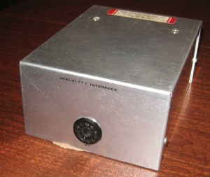
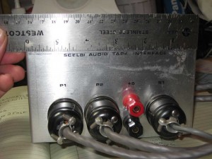
    Front-Cassette-Interface
    Height is obscured by the ruler, but it is 3 1/2″. I can’t recall where I read about it, but I think the lettering on SCELBI enclosures is rub-on Letteraset or equivalent. It was clear coated after being applied.

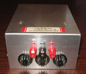
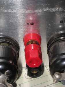
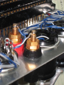
    Here are some pictures of the binding posts.

    Binding Post Front

    Binding Post Front

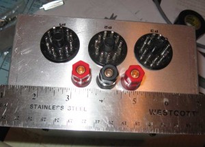
    Binding-Post-Rear

    This picture also shows how the opposite pairs of pins on the edge connector are bent and soldered together. This can be seen toward the right of picture where a couple of wires connect to the edge connector.

    I have images of the cassette interface unit at the CHM and the wiring was done with two color purple and red wire, so the tech must have used whatever he had available. The edge connectors on that CHM unit are blue and marked 67040 over 6748. It’s hard to tell from the images that I have, but I think those CHM connectors had a single row readout. The overall form of the connector design in the CHM unit seems to be a fairly close to match these AMP units. However, the color is wrong and the wire wrap lead length of .75″ is likely to be too long.

    Inside the SCELBI Cassette Interface

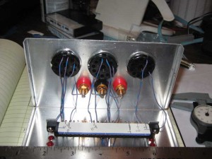
    Many SCELBI ethusiasts have found the image of the Audio Cassette Interface in the Computer History Museum’s catalog page. I recently had a chance to check out an extremely rare original example and took the opportunity to take some pictures and measurements. Here is how the front of the chassis is set up. Wiring follows the schematic. Note that this picture is actually taken upside down, as the cards are mounted to the top half of the enclosure.
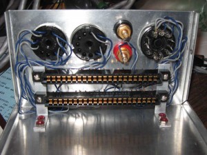
    Inside Cassette Interface

    Inside Cassette Interface

    Though the mechanical design is simple, building this chassis clearly involved a lot of manual labor. I wonder what would have happened if the SCELBI had started to take off like the Altair did. I think that Nat and Bob were very lucky to be able to move the company so successfully into publishing. The SCELBI Computer clearly would have required a complete redesign in order to compete with the coming wave of inexpensive, mass market, micro-computers.

    From this upside down perspective, the read card is mounted facing up, in the upper slot, and the write card, in the lower slot. There are holes in the bottom of the enclosure for viewing the LED on the read board and a hole in the rear for adjusting the POT, also on the read board.

    The binding posts for power and ground are very nice examples with heavy gold plating. Unfortunately, I couldn’t find any manufacturers markings on them.

    What is not so good, is that the horizontally mounted cards are not supported by anything other than the edge connectors. This means that rough handling could easily cause damage or connectivity issues, particularly with the rather long cassette cards. Many systems, such as the wildly successful Apple II, used non-supported peripheral cards in edge connectors, but the cards are usually mounted vertically so that gravity will help hold the cards in the slots.

    It’s not visible in this view, but the pins from the top and bottom rows of each edge connector are soldered together in each position where there is a wire connected to the edge connector. I’m not sure why this was done, as no signal lines were connected to the top side of the edge connectors on the cards. I also got to look at a TTY enclosure. That enclosure had a different type of connector with single row of pins installed.

    When I get a chance, I’ll be posting more images and make up drawings with measurements.