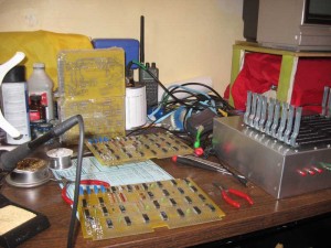
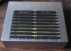
When checking out a new SCELBI 8B, make sure that there is a 8008 installed on the CPU board. Things will go a lot smoother. 🙂
Category Archives: 8008
SCELBI Output Port Wiring
The SCELBI uses an 11 pin Amphenol connector for output ports. The hardware manuals specify:
That leaves pin 10 as “open”. When I first built the SCELBI-8H reproduction, there was some speculation about possibly using 10 pin for +5 volts, instead of leaving it open. At the time, I thought this probably wasn’t a great idea, because of possible losses over the cables and connectors. However, the same concern really also applies to the ground wire, which is connected.
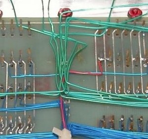
During research into the SCELBI peripherals, I discovered that the CPU SYNC signal is used on the Oscilliscope interface and the Cassette interface. We have some evidence that at least one SCELBI chassis had sync connected to some (or possibly all) output ports. Since only pin 10 is available, it makes sense to use it for SYNC for these I/O cards.
This is a crop of an image taken by Jack Rubin at the CHM a few years back. The red wire seems to be connected to the SYNC pin on the CPU card and runs back towards the I/O connectors.
Film Capacitors for the SCELBI Cassette Card
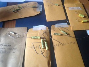
I found a nice selection of old film capacitors for my SCELBI cassette interface build at surplussales.com. Here is an image of what I ordered.
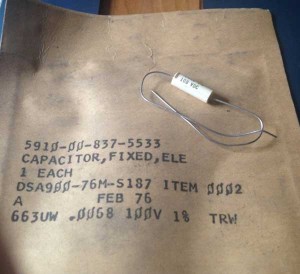
I tested all of these for capacitance, all have the correct value. I did not measure ESR. The most interesting of these are the TRW caps that came individually packaged in brown paper.
The West-caps are oval shaped, not perfect for the SCELBI cassette interface, but they will do, at least for now. I bought two versions of the .0068uF size, and will probably use the Mepco versions, since they are closer to the original yellow caps, than the TRW versions. My selection criteria, was to try to find something rated around 100V, with axial leads, and less then 1″ long.
I also found a great deal on Amphenol 78S11 type sockets at the same place. Since starting on this project, this deal, is the best price I’ve seen on this style socket. I bought enough to complete all the peripheral chassis that I plan to build. Here is my surplussales invoice, with parts numbers.
I have two more parts orders due to arrive this week, at which point I should be able to complete my 8B and start on the cassette interface.
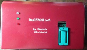
ME1702 programmer artwork
“C” language 8008 emulator, debugger, disassembler source posted
Here is a link to the “C” language source for my 8008 debugger/disassembler. Though it has been a while since the code diverged, the core 8008 instruction emulator is essentially the same as used in my Macintosh OS/X app. Some of the output could be cleaned up a bit and I want to add an emulated cassette interface, but I think it has been pretty useful in creating and debugging 8008 software.
It takes 1 or 2 arguments, an Intel HEX file with the program to debug and an optional starting address (in decimal).
Here is a list of commands.
Thanks to Cameron Cooper helped me with the initial conversion of the step display to include instruction nmumonics.
Things to do – add support for emulated SCELBI cassette interface.
SCELBI Cassette Interface Software
Though I have complete description of the Cassette Interface PCBs, hooking those boards up to the main SCELBI chassis requires more research. One key to understanding this hookup, is understanding details of the software. The MEA software was written to work with some specific connections between the SCELBI I/O ports and cassette interface cards. With changes to the software, this could be done in a number off different ways. Since I want to run standard MEA software, I need to hook up the hardware to match the original configuration.
The cassette interface software driver resides in page 77 of a SCELBI set up with the MEA software. I have found two sources of this MEA cassette interface software driver. First is the hex file for page 77 of MEA that Cameron Cooper and Mark Arnold reconstructed. This file can be downloaded from scelbi.com. The other source is SCELBI Newsletter #3, which also can be found on scelbi.com. In order to figure out what the relationship between these two images is, I took the hex file of page 77 and disassembled it and then compared to the listing in the newsletter. It turns out that the two drivers appear to be identical. Since the newsletter listing, includes comments, it greatly helped the understanding of this driver.
While I’m not completely done investigating, I have been able to create a lightly commented source listing that can be assembled with my version of the AS8 assembler. Once I’m done investigating and have a cassette interface hooked up and working, I’ll be sure to post the description of the connections.
SCELBI Cassette Interface Source
SCELBI Cassette Inteface Assembly Listing
Stay tuned for an upcoming blog report, where I’ll describe what I did to create an 8008 disassembler, as well as post the source for it.
First Pass at Cassette Interface BOM
Here is my first pass at BOM (bill of materials) for the SCELBI cassette interface.
Initial Cassette Interface BOM
This is taken from the schematics, with some reference to images and my PCB layout. I haven’t check all the resistors and capacitors to see if what is populated on the boards matches the schematics. The sum and count rows in the document compare the count of devices in the document (sum) with the number (count) that are found in images of the original circuit boards. The intention is too make sure that all devices are included in the document.
Other than the schematics, I haven’t seen any original documentation for the SCELBI cassette interface, though we do have the driver for MEA and there is some articles about the cassette interface in the SCELBI newsletters (available at scelbi.com).
The most unusual device is the 72741 opamp. This is a classic 741 opamp in a 14 pin DIP package. I have been able to find a few on eBay. If you want to use Ohmite carbon composition resistors, much to my surprise, it appears that Mouser has everyone of these values in stock.
I’ll have to research the capacitors a bit more, but I’m sure that something that will function, can be found for each of these values.
Since I haven’t built one and haven’t verified all the discrete components by examination of an original card, there could be some problems with this first pass BOM. In particular, I don’t know what specific transistors and diodes were used. Based on usage in the circuit, I expect that pretty generic versions will do the job, so that is what I listed in the BOM.
The last part that may cause you to scratch your head, is the DIP relay. In the past, I found a matching part is still made, but I failed to record the manufacturer and will have to dig around to locate it again.
Backlog Building/Building Backlog
Projects are starting to back up on my bench.
I’ve never been that excited about repetitive work, but I have a few things to catch up on, before moving on to the “new” stuff I have on the backlog.
Right now building the 2nd set of “core” boards is in progress. When I first built the 8H, I bought enough parts for 2 sets of “core” boards. However some of those parts got used up in other projects. I’m building with what I have and when I get everything put together as far as I can, I’ll order whatever I have run short of. At the same time, I’ll put together a BOM for those “new” boards in the background and get what I need for those. Postage costs will really kill you, if you are constantly ordering 1 or 2 parts at a time. That is something I try to avoid, though often unsuccessfully. Here are a couple of facts that will give you an idea of how many parts that I have gone through, while building two SCELBIs.
If you like to build complex gadgets, the SCELBI’s are amazing projects. The best part is that they are relatively well engineered, so if you work carefully, once completed, they usually work. I can’t think of any project that has given me more pleasure. Even, the repetitive work of making the second set of “core” boards has been fun, at least once I found the gumption to start on them.
SCELBI Chassis Build Tips
I’ve been working on moving my SCELBI 8B to one of Corey’s custom chassis. Here is what it looks like at the moment.
I figured I’d share some SCELBI chassis preparation tips here.
1) To prevent rub marks, use masking tape to protect any areas of the sheet metal that may experience contact with your tools.
2) Keep in mind that during this period, American engineers exclusively used imperial dimensions.
2) If you are converting a BUD AC-413 chassis you must first cut out the backplane area and drill holes for the I/O ports. If you have one of Corey’s chassis you can skip to step 6.
3) I recommend, making patterns for both top backplane opening and rear I/O connectors. Then attaching the patterns to the chassis when making the cuts.
4) The hole in the top for the backplane is set back 1/2″ from the front and centered from side to side. The dimensions Corey used for top cutout of the 8B is 6.375″ deep by 8.875″ wide. The 8H is 1 slot shorter in depth. Slots are spaced by .75″, so 8H would have .75″ less depth. 6.375-.75 = 5.625 There isn’t a lot of room for error when mounting the backplane, so try to be precise as possible. If done right, the edge connectors will just fit through the opening, when the backplane is mounted underneath. If you have doubts, you can add the edge connectors to the backplane and measure the area needed to fit them and work from there.
5) The I/O holes in the rear can be punched out with a type 732 GreenLee chassis punch, sized 1 11/64″. Be aware that type 732 comes in different sizes. Prior to punching you need to make a series of 1/2″ holes to mark the center of each opening. These holes are on 1 3/8″ centers. There is more on these dimensions on this blog posting.
6) Once you have pilot holes for the I/O connector and the backplane opening cut out, you can punch out the final I/O connector holes. When using the punch, the cutting edge should be on the outside of the chassis, so you don’t mar the exterior surface. Don’t mount the I/O connectors until all cutting on the chassis complete. I don’t know if it makes a difference, but I lubricate my Greenlee cutter with spray silicone lube.
7) If you have a front panel, you can use it as a guide for the toggle and push button switch holes. Simply clamp it to the front of the chassis. There should be even overhang on the sides and the bottom of the chassis should be flush with the bottom of the front panel. The holes for the toggle switches are 1/4″ and the push buttons are 9/32″
8) Mounting the backplane is one of the most critical aspects of building a SCELBI chassis. Solder on all your edge connectors before proceeding, but do not mount the card supports.
9) Note that the current version of my 8H backplane does not have predrilled mounting holes, so you will have to drill holes through both the backplane and chassis together, instead of using the backplane as a guide.
10) In order to drill the backplane mounting holes, position the backplane on the underside of the chassis. The edge connectors should protrude through to the top of the chassis. I use card stock to shim each side of the backplane so it is centered and doesn’t move. I use #6 screws to mount my chassis, so I used a 9/64″ drill bit. Don’t confuse the holes for the card supports with the chassis attachment holes. For the 8B, I start by using the backplane as a guide to drill 4 holes in the chassis. These holes are the ones on each back corner, and the ones on each side closest to the front.
11) I then move the backplane to the top of the chassis and use the holes I just drilled to correctly locate the backplane. Put 4 screws through the 4 holes you just drilled to keep it in position. If you have an 8B, you can use the backplane as a guide to drill out the remainder of the chassis support holes.
12) Note that the support of the front edge of the backplane is not by holes through the backplane, but by the nuts of 7 supporting screws which overlap the front edge of the backplane. These 7 holes must be located at the edge of the backplane, so that one edge of nuts will hold the backplane in place.
13) Any burrs left on the holes can be scrapped off by twisting a sharp, large bit in the center of the hole. Do this by hand, not in a power drill. The aluminum is soft and it doesn’t take much to remove these burrs.
14) Remove the backplane before you add the Amphenol I/O and power connectors. The rings that hold these on, do not seat completely and it is an exercise in frustration to try to make it so.
15) Now that all the holes are drilled, mounting the backplane to the bottom of the chassis is pretty straight forward. Just don’t over-tighten the nuts or you could crush the substrate.
SCELBI Cassette Read and Write Cards Ordered!
It should take a little less than two weeks for them to arrive. During that time I’ll continue work on moving my 8B system from a temporary chassis to one of Corey’s custom chassis.
I started on the read card in December, so these two cards took about 7 months to do. I guess I might be slowing down a little bit. On the other hand, I’ve had a lot of other things in progress at the same time.
Assumming that these two boards work out, this leaves only the keyboard and the 2 oscilloscope cards left to do to complete the entire SCELBI board set. The keyboard and scope analog cards should go pretty fast, but the scope digital card is a fairly complex double wide card, so it will probably take a while.

