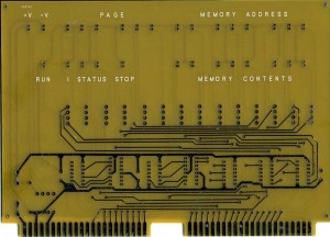
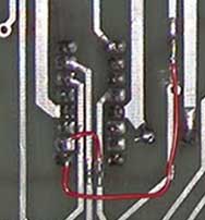
8B Assembly Manual Mistake Discovered, the hard way

I’ve started working on building up a second set of the “core” SCELBI boards. I call the boards that are shared between the SCELBI 8B and 8H, the “core” boards. These are the front panel, the cpu, the DBB, and the input boards. When I built my prototype 8B, I didn’t bother to make new “core” boards, I just borrowed them from my 8H. Now that I have a new set of the “core” PCBs in stock, I figured that I would make up a second set, so that I could run both the 8H and 8B at the same time.

As part of the building of these new boards, I figured I’d use the 8B manual that I am in the process of digitizing. Yesterday, after completing the front panel board, I discoved that all my LEDs were installed backwards. The manual states:

The anode of the L.E.D. (shorter lead) goes in the top most hole (furthest away from the card connector). The cathode of the L.E.D. (longer lead) goes in the bottom hole.

This is actually the reverse of how LEDs are made – the cathode has the shorter lead, not the anode. I didn’t encounter this issue when building the board for my 8H, because the 8H front panel instructions were written for the old style LEDs in the cans, so I had to figure out the right way to connect them without benefit of the SCELBI manual. You would think that with all the projects that I’ve done, that I would remember how LED’s are constructed and connected. However pinouts are the sorts of details that are easily found in reference material, so I don’t put any effort into memorizing pinouts of anything.

As far as the newly digitized manual goes, one of my intentions is to add content and clarification when it is missing, but maintain the “character” of the original manual. I think, in this case, I will correct the text and add a footnote that explains how the original manual was wrong.

Cassette Write Board Verification in Progress

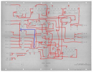
Verifing the layout against schematics, is an important step in my reproduction process. My usual method of schematic/layout verification is to print a copy of the schematics then mark each trace as I verify the connection with a marker. This time I did it all digitally using photoshop as a replacement for the paper.

Tape Write Schematic Markup

Tape Write Schematic Markup

The blue layer notes omissions, corrections or clarifications to the schematics. Most of these are due to the mistakes made in the initial rev of the board, which were later corrected. The version of the schematics I have access to, does not have those changes incorporated into them.

During this process, I did find a number of traces that were hidden under chips. Omitting these traces is an easy mistake to make. I missed one of these on the memory expansion board. This time, I am reasonably sure that I found them all.

New Version of SCELBI OS/X Emulator Released

The release of a new version of my OS/X SCELBI/8008 emulator was motivated to provide support of the Modified Creed Monitor for the 8008. To do this, I added menu options to support to optionally setting (input) and clearing (output) the most significant bit of input and output serial data. For the MCMON, the input menu for set the bit should NOT be set. The output setting doesn’t matter.

Another SCELBI Cassette Write Board (with logic changes/fixes)

While working on the SCELBI cassette write board, I found some issues which were reported in this blog post. I found that I had detailed images of a second cassette write board, and it looks like the problems on that first board that I looked at, were corrected on the second board.

The first board is the one found at the CHM, and was photographed a while back by Jack Rubin. The serial numbers on the SCELBI associated with that unit are in the single digits, so that unit was apparently a very early unit. The second, corrected board, was part of the collection of Nat Wadsworth. I am only aware of one other cassette interface, but I don’t have images of that unit. I don’t know how many were made before the corrections were made.

Here are partial images of the front and back of relevant sections of both boards. Red arrows on images of the Nat Wadsworth unit show where visible changes were made.
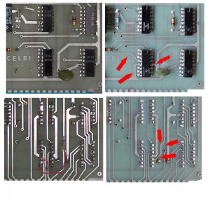
Cassette Write Board Changes

Cassette Write Board Changes

Note that the changes are somewhat different than the what was done in rework on the CHM unit. These changes don’t match the schematics, but I was able to piece together what was done and why.

First, let’s talk a bit about what is going on, by reviewing this section of the schematics.
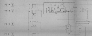
Cassette Schematics - Z1

Cassette Schematics – Z1

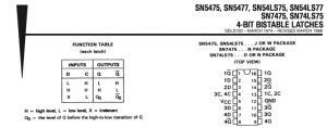
The chip associated with all these changes is a 7475, a part that has 4 bi-stable latches. Here is the key part of the data sheet – the truth table and the pinout.
7475 Data Sheet

7475 Data Sheet

The function of this chip is pretty simple. Whenever clock input 13 is high, the chip’s output pins, 16 and 15 follow the input on pins 2 and 3, respecitively. Also, output pins 10 and 9 follow inputs 6 and 7, respectively, when clock input 4 is high. When inputs 4 or 13 go low, the associated pair of outputs, are “frozen” or are “latched” into their current state at the time the clocks inputs go low. Note that there are normal and inverted outputs for each latch.

In the schematics, three inputs are connected from a SCELBI output port to this chip. There are two data bits and the port’s output strobe. The output strobe is a high going pulse that occurs when an 8008 OUT instruction addressed to this port. The data bits are connected to the SCELBI write data bus, so will change rapidly, as the 8008 writes to memory or output ports. The strobe is connected to the clock input (pin 13) of the 7475 latches 1 and 2. This circuit allows the 7475 chip to capture 2 bits of the SCELBI output data onto latches 1 and 2 whenever an out instruction is directed to the output port connected to the cassette interface.

What about the two other latches of the 7475? In the schematics, the clock (on pin 4) for outputs 3 and 4 is not connected. What usually happens on unconnected inputs of 74XX series logic is that the input will “float” high. As mentioned before, if the clock inputs are high on the 7475, then the outputs will simply track the state of the inputs. The 3rd latch of this chip is not connected or used. However the 4th latch (pin 7) is connected to the strobe input, so the output will follow the strobe all the time. The inverted output on pin 8 is used as a clock elsewhere on the board. The function is a buffer and inverter of the strobe input to the board. Note that letting an input “float” high is not a good design practice and it’s possible that clock input on pin 4 was directly tied to +5 volts, which is connected to pin 5. It is not connected on the bottom of the board, but could be connected on the top of the board, which is obscured by the chip. The only way to know for sure, would be to use an ohm meter to determine if pin 4 is connected somewhere by a trace that is obscured by the chip. I don’t presently have access to this board, which is in storage at the CHM, so I can’t do this. My best guess, based on the extensive use of pull up’s elsewhere on the SCEBLI boards, and lack of a connection in the schematics, is that it was left to float high and was not connected.

As mentioned in the previous blog post, the first version of the layout has two significant problems.

1) The strobe output wasn’t connected to pin 7 of the 7475. This is rectified with a jumper wire.
2) The output on pin 8 (which is the inverted strobe signal), is not correctly connected to the rest of the circuit. This is rectified by a cut and jumper as can be seen in the image of the back of the board.

So what did the people at SCELBI do, to fix the problems in revised layout.

1) Power and ground connections to the chip were rerouted to make room for signal traces that needed to be added.
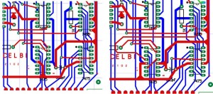
2) The inverted strobe output which was supposed to be on pin 8 was moved to pin 11, which is the inverted latch 3 output. This was done to make it easier to connect to the rest of the circuit. It was also disconnected from the strobe input connection.
3) The floating clock input on pin 4 was tied to an existing pull up resistor.
4) The latch 3 input was connected to strobe input by running a trace under the chip to pin 13, which was already connected to strobe. I actually can’t verify this change, but I can be fairly certain that it exists, since the circuit would not work without this trace.

Note that this change to use latch 3 instead of latch 4 for buffering and inverting the strobe is not reflected in any schematics that I have seen. The schematics actually don’t match either of the boards described in this description.

If you look at CAD images of this section of the board, you can see how the changes were made. Blue traces are on the bottom layer and red traces are on the top layer of the PCB.
Write Board Changes

Write Board Changes

I have repeated this sort of exercise numberous times over the years to solve various inconsistencies in schematics and PCB layouts in a number of vintage computers. Understanding a vintage design frequently requires detailed detective work, but with time and patience, most mysteries can be solved.

One last comment about the nature of the problems with this board. Of the thirteen SCELBI boards that I have investigated in detail, this is the first significant layout problem I have run across. There is an issue on the DBB board with a single missing trace. In this case, the connections to the 7475 were botched and had to be redone. This is a very unusual and unexpected mistake from the engineers at SCELBI.

Cassette Write Board Rework

More progress on the SCELBI cassette write board. I have figured out the reason for the rework seen on at least one board.

Cassette Write Board Rework

Cassette Write Board Rework

There are two wires and a cut on this board. In both these cases, the PCB didn’t follow the schematics. Both changes are related to chip Z1 connections.

In case 1, pin Z1-7 should have been connected to Port A, pin T. Port A, pin T is already correctly connected to Z1-13 and Z2-13 and Z2-4. I’m not sure if this omission was on purpose or not. Routing to Z1, pin 7 would require running a trace on the top of board, from Z1-13 out the top of Z1 around the outside of Z1 to Z1-7. This would also require re-routing a couple of other traces on the top side of the board to make room for this new trace. It’s very unlikely, but possible the layout person didn’t want to mess with this and decided to just require the board builder to add a wire.

In the second case, Z1-8 is not connected to Z11-3. Instead Z11-3 is connected to Port A, pin T. The fix requires cutting the trace from Port A, pin T, after it splits and runs through a via to go to Z2. Then a wire can be soldered from the cut trace to Z1-8. This is clearly a layout error.

I still have at least one more mystery to solve on the cassette write board, before I’m done with it, but the layout is shaping up real well.

New batch SCELBI FP, CPU, DBB & Input PCBs on order

I finally sold my 19th set of SCELBI boards. There were 20 sets made in the original batch for the 8H that were made in January of 2013. There were about an even number of 8H and 8B sets sold, and the boards I’m reordering are common between the sets, as I still have plenty of the boards that are unique to each system. There are only two differences between these new boards and the original set of boards.

1) The size of the holes for the zener diodes is being made a little bigger. Note that if you can find them, the leads for the original style zeners in the cans will fit in the original holes, but more modern zeners have thicker leads may not. Older boards will work fine with the more modern zeners, but the holes will have to be reamed out a bit and the leads soldered on both sides of the PCB.

2) This time around, I’m adding a silkscreened legend on the front panel board. The original SCELBI front panel boards came both with and without the legend, but I see more original units with the legend. This is why I’m adding the legend to this batch. When I made the first set, I thought that only early boards that were made before the advent of the aluminum front bezel had the legend. Later on, I discovered that a number of systems with the front bezel, also had a front panel board with a legend silk-screened onto it.

CHM moves the PROM card in their SCELBI-8B into the correct slot

The CHM has the chassis of a SCELBI-8B on display in their micro-computer room. This chassis has 2 4K SRAM cards and 1 PROM card installed in 3 of the 4 memory slots. The PROM card has the standard EPROMs for MEA (monitor, editor, assembler) installed. For the longest time, that PROM card was in slot 8 of 9. This is incorrect, because of fixed addressing of the slots, MEA can only run out of slot 9.

Earlier this month, they moved the PROM card to the correct slot, slot 9. It was interesting from to hear from their curators about how carefully they documented this simple move for their archives. They told me, “We have a note in the permanent record for the SCELBI, including photographs.”

SCELBI 8H – boot up/debugging tips

I’m working on a 8008 amateur radio project for the VCF east. This project needs 2 input and 3 output ports, plus a serial input port for boot loading.

I have a working SCELBI 8B. The 8B has a memory editor in PROM, which makes entering a bootloader much easier than on an 8H. However, my SCELBI 8B is mounted on a temporary chassis that still only has a minimal number of I/O ports connected. When I build the final reproduction 8B chassis, I plan on connecting the full array of I/O ports. Until then, the port requirements for this VCF project dictate that I use my 8H for that application.

At this point, I have no PROM on the 8H. Downloading is through a 37 byte bit banged serial I/O driver that must be toggled in one byte at a time, using the front panel. It typically takes me about 30 minutes to initially toggle in the bootloader and boot the chassis with an application. What follows, are some tips that make booting the SCELBI 8H less troublesome.

I frequently make mistakes toggling in the bootloader. Troubleshooting a mistake can be difficult on the SCELBI. It used to take me quite a bit of time to correct these toggling errors. I have developed some approaches that make troubleshooting the bootloader fairly quick and very straight forward.

After toggling in the loader, I set the “L” register to a known location past the end of the boot loader, but in the same “H” page. This saves the time of having to toggle in a new value into the “H” register. I’ll connect the serial device that will be used to download the application, which is my case is usually a laptop computer. I start the terminal emulation program, and run the boot loader and enter a few characters using the keyboard. After typing in a few characters, I’ll interrupt the SCELBI and use the decrement L instruction (061) to back up the L pointer. Then I’ll use the load A from memory instruction (307) to read the contents of what I’ve written and verify that the character that I typed went into memory correctly. Entering a few characters with the keyboard before downloading the full application, allows you to skip changing the H register to point to the start of the application, while verifying correctness of the bootloader.

If the data doesn’t look right or isn’t making it to memory at all, I’ll toggle in the jump instruction (104 XXX XXX) to jump to the start of the bootloader. I can then single step through the bootloader to make sure I’ve toggled in the correct code. When you enter a loop, just verify one pass of the loop. After verifying by stepping through one pass, toggle in the jump (104 XXX XXX) instruction to go to the next part of the bootloader. This is much faster than stepping through the loop until it exits or reading back all of the program by reading memory indirectly with the HL registers and the front panel.

If I find a mistake, I’ll toggle in the load L immediate instruction (066 XXX) to point HL to that location. I’ll then use the load A from memory (307) to double check the contents of that location. If it is wrong, I use the load memory, immediate instruction (076 XXX) to correct it.

Next, reset L to somewhere other than the middle of your bootloader, run the bootloader and try typing in a few more characters. Once you are able to enter characters correctly, then point HL to the starting address of your program and download it. Be aware that if you forget to move the HL pointer, you may overwrite the some part of the bootloader. I have found that if you make this mistake, all is not lost. The SCELBI usually halts after destroying just a few locations of the bootloader, not the entire thing.

After sending the program down to the SCELBI, I do two checks. First, I check that the HL registers are one past the end of the program by loading A from memory (307) and monitoring the address read. If it is correct, I’ll decrement L (061) and load A from memory (307). The data read should match the last byte of the downloaded program.

Once the bootloader is in memory, try to avoid overwriting it. If your application doesn’t touch that part of memory and you don’t power off, it can be used to load a new application or a different version of the bootloader that can be located elsewhere in memory.