A Side Project

One of the things that I have been hoping that I’d have time to do was to fully digitize the SCELBI manuals and add notes for the “modern” recreater. One of the main obstacles has been the extremely poor results from OCR software that I have used in the past. Well, I finally bit the bullet and spent some money on dedicated OCR software and am getting somewhat better results.

I’ve been working on the card assembly portion of the 8B build manual. So far, I haven’t added any modern reproduction notes, but have worked on getting the original manual transcribed. Here is what I have done so far.

8B hardware book

Let me know what you think of this draft.

Project Review – ME 1702/A Programmer

This is follow up to my previous post about building a Martin Eberhard 1702/A EPROM programmer.

In this post, I will share some more details about this project. This is not a kit, but Martin occasionally sells a PCB with a programmed PIC micro controller. Extensive instructions, including a parts list with recommend suppliers can be downloaded. Martin has sold several batches of these PCBs over the last couple of years, and I purchased a PCB and PIC from his most recent batch.

The programmer has a built in RS232 interface and can be controlled by any computer with terminal emulation software that supports capturing text to a file and sending text files. I use CoolTerm on a Macintosh for this functionality

All the parts have either Allied or Digikey parts numbers, so it is a pretty simple process of ordering your parts using Martin’s bill of materials. In my case, I found that I had some of the more vanilla parts already on hand, and I saved a few bucks by using what I already had. There are quite a number of different parts required. Usually when I order parts, I order spares of everything, but in this case, I ordered exact quantities of most parts, as I figured paying the postage for one or two damaged parts would be cheaper than ordering spares. In my initial order, I forgot to order one part and didn’t order enough quanity of a second part. These were my mistakes, as Martin’s bill of materials are right on.

I also made a couple of substitutions, one that didn’t work out so well. In the case of the DB-9, I purchased a male connecter instead of female. This is because most of my other devices with DB-9’s, use male connectors and this would allow me to use existing cables. In the case of the MAX232, I substituted a MAX202. The MAX202 has the same pinout as the MAX232, but uses .1uF capacitors. I had both the MAX202 and .1uF capacitors on hand, so this was a no brainer substitution.

The one that didn’t work out so perfectly, was the power supply plug, the Apple 1 uses the same form factor .156″ 6 pin header, so I used a connector from my stash of Apple 1 parts. Unfortunately the Apple 1 is a slightly different style, so the pins I bought, using the 1702/A BOM were not correct for the Apple 1 connector. I would have used Apple 1 pins, but I was out of them. I should have refered to my Apple 1 BOM in order to get the correct pins for my connectors. I was able to make do with the combination of connector and pins, but it’s not as secure as it should be. For now I have used silicon glue to secure the connecters to the housing. Next time I put in an order, I’ll get the correct connector and fix this issue.

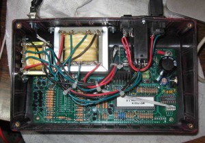
I only have three colors of 18 gauge wire, so my color coding is not optimal. I used black for black, red for white and green for everything else. For the wires that go to multiple locations, I recommend running a pigtail and connecting multiple wires to the pigtail and covering the connection with heat shrink tubing.
Inside ME 1702/a Programmer

Inside ME 1702/a Programmer

Cutting the case openings was pretty time consuming. I made the cut outs by drilling holes in the corners of each cut out using the template from the manual. I then used a coping saw to connect each hole. This was followed by a lot of hand filing and tweaking with a dremel type tool with a cut off wheel attachment. The cut off wheel really helped me keep the straight edges, straight. Keeping edges straight would have been much more difficult with a regular grinding bit. For my first round of 1702 programming, I had borrowed a unit that had been painted MITS blue. That looked pretty nice, so I had to fill the sprue location in the front of my chassis and slap some paint on it. I’d guess that an expert could do it faster and better, and the paint job is pretty crusty, but I’m fairly happy with the result. I’m considering improving the paint job and making some decals or screen printing the chassis with a logo and lettering in the future.

One of the more time consuming parts of this project was wiring the transformers. Anyone that has done an Apple 1, will immediately recognize what is going on and be able to figure it out. During assembly, I made one mistake, and that was wiring the six pin .156″ power connector. That caused a blown fuse, but apparently no other damage. Make sure you know which end of that connector is pin 1 – the description is clear in the manual, but I guess I didn’t read it closely enough.

The instructions include rather detailed checkout instructions, and I recommend following them. My unit has two voltages that are a bit higher then specified in the manual. The first was found during Step 10, “Test High-Voltage Power Supply Control”. The voltage on the right side of R95 was just a shade over 75 volts. It is supposed be the combination of the drop over two zeners, 15 and 58 volts, which should have made the result about 73 volts. In my system, the drop over the 58 volt, 4758 volt zener, was just over 60 volts. This added to the 15 volt drop of the other zener resulted in the >75 volt reading. It could be that zener was out of spec, but I decided that it was probably close enough and moved on.

The other slightly high voltage was found in step 14, “Test High-Voltage Logic Signals”, where I found that logic low on the data signals was around .84 volts, when the manual said it should be under .7 volts. I looked at the schematics and measured voltages at several points in that circuit and couldn’t find any obvious issue. Looking at the 1702 spec, it looks like programming data low is -46 to -48 volts. Since the supply is 48 volts, that gives 2 volts of margin, so it should be fine. I decided to move ahead and try programming some actual devices.

I started with a part that probably had a burned out data bit. I did a number of experiments and could read the part and program each bit (except the bad one) and address successfully. Then I moved onto another part and proved out the bit I couldn’t test with the first part.
ME 1702/A Programmer

ME 1702/A Programmer

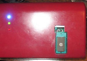
My Martin Eberhard 1702/A programmer appears to be working perfectly. I don’t have much mileage on this newly built 1702A programmer, but I can comment on the experience of using my friends, a few months back. At the time, I needed to program 16 devices for the SCELBI PROM board. I had very few issues during that session. I found two parts that didn’t blank check. Since I don’t yet have an erasing light, I don’t know if these parts are bad or just have been programmed before they got to me. I was able to program 16 parts that did blank check correctly with only one hiccup. That was one part that apparently hung the programmer, or was just taking a very long time to program. I power cycled and repeated the operation with the same part and it completed normally. I’m very impressed with this programmer, as well as the reliability of the 40 year old NOS 1702 EPROMs that I have had such good luck with.

Looking forward, I now have the capability to program the SCELBI keyboard and oscilloscope interfaces without having to borrow friends equipment. I expect I’ll have to go through several iterations of those drivers, since we haven’t found the original SCELBI software. I’m interested to find how these old devices will stand up to reprogramming.

I consider that building this programmer a medium sized project. Except for my own projects, I haven’t built any micro-controller based kits before. This one was really fun. I wouldn’t recommend it for a beginner, but someone who has been restoring or reproducing 70’s era computer systems for a while should have a lot of fun building this very useful device.

The cost will vary depending upon what you can find in your stash, but I think you should be able to build one of these units for $160-$180.

1702/A Programmer Project

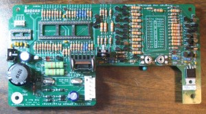
I’m in process of building one of Martin Eberhard’s 1702/A programmers. I just finished soldering the PCB. and here is what it looks like.

1702 Programmer PCB

1702 Programmer PCB

The ZIF connector and three LEDs are mounted on the back side of this board, which will be mounted upside down in the enclosure. Martin did a great job with the layout – the overall structure of the layout reminds me of the Apple II’s layout, which, in my opinion, was a masterpiece in it’s day.

There are a lot of discrete components, but that is because of the high programming voltages required. At one point, I searched and couldn’t find any suitable integrated circuits that will handle the 50+ volts required to program this part.

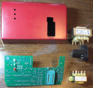
I also have made the cutouts in the case and have painted it. The case is a plain black styrene plastic, so the paint really improves the look. Here it is, along with the two transformers and the power entry module. I have everything I need to finish it, except for the DB-9 serial port connector, which is still on order.

1702 Programmer - Major Components

1702 Programmer – Major Components

I need to go back and check the detailed manual, but I think the next steps will be wiring the transformers and testing the power supplies.

SCELBI 8B panel logo update

In a previous post I commented that the Helvitica Bold was an exact match for the SCELBI-8B panel logo.

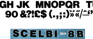
Well I went to digitize a recreation of the logo for eventual silk screening on a front panel and I found that I was mistaken. The panel characters are wider than the Lettraset letters and I couldn’t find a better match in the Lettraset catalog. Helvetica Bold was the closest that I could find, but as you can see, it’s too narrow.

Helvetica bold overlaid on top of SCELBI-8B logo

Helvetica bold overlaid on top of SCELBI-8B logo


These characters were scanned from the Lettraset book, scaled and placed over the top of the original lettering in Photoshop.

However, I was able to resolve the issue by stretching the scanned Lettraset letters horizontally, one at a time, in Photoshop.

Stretched Helvetica

Stretched Helvetica

I think the result is about as nice a match as you could hope to have.

SCELBI Update

A quick update on status of the reproduction SCELBI project. The cassette read card is about 98% done. I could get boards made today, but before pulling the trigger, I’ll see if tweaking the layout a bit in a couple of places will make it match the original layout a bit better. I have obtained some audio files made on the tape interface of an original SCELBI, so I’ll be able to try testing it, without having to build the cassette write card.

I’ve started on the cassette write card PCB layout. First step of the process is to position components to match the component placement of the original card. This is largely done, but I’m going over positioning a few more times before laying traces. It’s best to get component placement as accurate as possible before starting on placing traces. Once you start laying traces, moving components around becomes a bigger effort.

There are a couple of unusual components on the write card. There is the SN72741, which is a single LM741 opamp in a 14 pin package. In looking around, those are scarce, but still can be found. There also is a relay in a DIP package, but like so many electo-mechanical components, it looks like those are still made. The relay is used to enable remote control of the tape drive. Some tape drives of the time had remote control for on/off.

As far as supply of PCBs for the main computer goes, I’m down to one complete kit in stock. This can be either the 8B or 8H. To be a little clearer, I only have one each, of the four boards that are in common between the 8H and the 8B. When this set sells, I’ll reorder those boards that I am low on, but it might take as long as a month or two to restock.

keep on vintage computing…

Improved Apple Teletype Emulation

A previous post showed how I attempted to connect the SCELBI TTY to an Apple IIe with an old serial card that supported current loop. Well I’ve been working on some of the issues and now have it working good enough to post some of the details. With the standard Apple 80 column scroll routine, I can only reliably get 8 lines to scroll at 110 baud, but it’s working pretty decently, with that limitation.

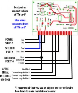
First of all, here is how the TTY card is connected. The standard SCELBI MEA software assumes these port assignments.

Apple Serial To SCELBI TTY Connection Diagram

Apple Serial To SCELBI TTY Connection Diagram

If you try repeating this experiment, be aware that there are two versions of the Apple Serial Card firmware,. However, since I don’t use the standard driver, it doesn’t matter which version you have.

The simple TTY emulation source code can be downloaded from www.willegal.net/appleii/ttyemul.asm. It is written to use an assembler called DASM, which can be found and downloaded with a web search.

You can experiment with changing the window size by changing the second line in the program. Note that I started with a “hijacked” version of the original serial card driver, but it has been greatly modified. This code assumes a IIe with 80 column card. For display, I had a lot of issues getting CR not to send a LF, but still return to beginning of the line. I also implemented a bare bones bell that sounds only if no characters are coming in.

I suppose a custom “fast” scroll routine might help with increasing the window size, but I haven’t had time to work on that. I think I left enough of the original Apple II peripheral card software mechanism in place, that it wouldn’t be too hard to move the code to PROMs that would reside on the serial card itself. For now, it assumes slot 2 for the serial card, and slot 3 for the 80 column card. Let me know if you have any luck with this.

I’m using a modified version of this software as the basis for my Apple II RTTY software, but the transmit side of that implementation needs some work. I want to create a way to type in some canned strings for transmitting CQ with a call sign and so forth.

SCELBI PCB update

Here’s a brief SCELBI project update. There were 16 different PCBs made by SCELBI for the 8H and 8B computers. The current status of my reproduction efforts of each of those cards follows.

Main System Cards – working reproductions of all 10 cards types have been completed
Reproduced
1100 CPU – 8H/8B
1101 Data bus buffer – 8H/8B
1102 Input – 8H/8B
1103 Backplane – 8H
1104 Front Panel – 8H/8B
1105 1K SRAM – 8H
1106 Memory Expansion – 8B
1107 4K SRAM – 8B
1108 Backplane – 8B
1109 PROM – 8B

Peripheral Cards – 1 reproduced, 1 in progress, 4 haven’t been started
Reproduced
2104 Teletype interface*

In progress
2103 Audio Tape read

Not started
2105 Keyboard
2100 Oscilloscope digital**
2101 Oscilloscope analog
2102 Audio Tape output

* not as high as normal vector boards
** double width vector board

A pretty conservative estimate is that I’ll have cassette interface read and write cards completed and working in the first half of 2015. I’m kind of hoping I’ll have them going by VCF east, but I’m not committing myself to it. I’d like to complete the Oscilloscope and Keyboard interfaces by the end of 2015. It’s really hard to say if I’ll actually finish them by the time the year 2016, comes around.

Apple PROM board, MEA/Apple TTY emulation update

The SCELBI PROM board is working fine and I was able to create a small program in the editor and execute pass one of the assembler with MEA. I can’t completely assemble a program and run it until I get the cassette interface built and operating. Pass two of the assembler writes the output to cassette tape. I’ll have to hold up doing a video until I can get the complete package going. My impressions of the MEA package are quite positive. It’s not as elegant as later software you might be more used to. However, considering the time frame it was made and the platform is the 8008, it’s a pretty nice package.

SCELBI PROM and extra SRAM boards cost $50 each and are available now. This recent work also confirms that the TTY board is working fine and those are available for $30.

I’ve been using an Apple IIe in 80 column mode with a bit-banged serial serial card to act as TTY emulator. However there are a couple of fairly significant issues that need to be solved before publishing this teletype replacement solution. It’s usable for me, but there are some problems. The two issues with my current Apple II TTY emulation solution are:

  • 1)The Apple II isn’t fast enough to scroll it’s screen at the same time it’s receiving data in a bit banged mode. It drops a few bits from the next character while scrolling the screen. This means that I’ll need to come up with a special designed card to support 110baud current loop with a UART. Since I’m doing a new card, I’ll consider figuring out how to add paper tape support and possibly printer support, as well.
  • 2) In 80 column mode, the screen driver doesn’t support carriage return, without also doing a line feed. In other words, you can’t move the cursor backwards to position 0 on the same line, like a real TTY would when it receives a CR. I’ll have to look into a software fix for this, but it might take sending the cursor to home and then moving it back down to the correct position on the page or something like that.
  • SCELBI running MEA

    SCELBI running MEA

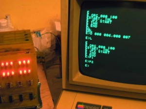
    This image shows the Apple IIe acting as a TTY for the SCLEBI 8B on the left. The screen contains a small program entered with the MEA editor. The listing of the program at the top of the screen has two extra lines at the end. The “D 000 006,000 007” is an editor command that deletes lines 6 and 7. The “L” command lists the text buffer. The last two commands “P1” and “P2” are pass 1 and pass 2 of the assembler. Pass 1 shows no errors. Pass 2 writes results to cassette tape. Since the cassette isn’t installed in my system it actually does nothing. If I had a tape, pass 3 would read the object back into the system so it could be executed.

    The “E”s on the left side of the screen should be the first character of the next line, but the Apple IIe can’t scroll fast enough to be ready to receive the first character of the new line, so it receives a partial character.

    yeah – MEA running on reproduction SCELBI 8B

    MEA dump memory command - Apple IIe used as TTY emulator connected to reproduction SCELBI 8B

    MEA dump memory command – Apple IIe used as TTY emulator connected to reproduction SCELBI 8B

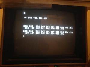
    Here is the dump of memory from the SCELBI PROM card from addresses 060-000 to 0600-037 as displayed on a 40 column Apple IIe, running some very simple TTY emulation software.

    To interface to the SCELBI, I’m using an Apple IIe with an old serial interface card. The Apple Serial Card is the first serial card released by Apple, and was intended to connect to serial printers. It included support for current loop and 110 baud rate. It’s the only thing I own, that supports that combination of baud rates and interface protocols. Be aware that this card is not the same as the very common Apple Super Serial card, which does not support current loop.

    For TTY terminal emulation purposes, I’m doing a major rewrite to the driver, as the default printer driver is not suitable for TTY emulation. I’ll post the emulation software and directions on connecting this serial card to the SCELBI TTY card as soon as I clean up a number of small issues.

    More updates on this exciting development to come soon.

    SCELBI PROM Board Progress

    SCELBI PROM Board

    SCELBI PROM Board

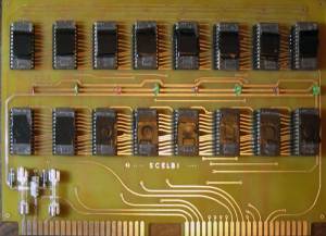
    The PROM Board is built, installed and appears to be running. However, it’s not completely checked out. I need to hack together a simple Apple IIe TTY emulation program that will work with Apple’s old serial card. That card is the only card that I have (outside of my SCELBI stuff) that will run at 110 baud, but it was designed for printing, so I couldn’t find any ready made terminal program for it. The standard PROMs on the SCELBI 8B assume either a keyboard/oscilloscope interface or a TTY interface at 110 baud. Since we don’t have the keyboard/oscilloscope software, I burnt the TTY software into PROMs.

    It should take me a day to two to complete the TTY/terminal program hack for the Apple II, at which point, I will probably make short video showing the capabilities of the SCELBI 8B minus the cassette interface.

    I used black tape to cover the windows on the EPROMs because I’m told that sunlight will erase them after a while.

    Meanwhile, you can run the software in my OS/X emulator by downloading the MEA hex file from scelbi.com and jumping to 060-000. In a quick trial, it appeared to work ok for me. Be aware that I don’t currently have the cassette interface emulated, so cassette operations will not work. Cassette emulation is one the things on my to do list.