SCELBI TTY and Apple II Serial Card Update

I now have SCELBI TTY cards in stock and will ship one to you for $30, shipping included. If you are interested send an email to: mike@willegal.net. Be aware that at this point they are not tested, so until I get one tested, I don’t guarantee that they will work without modification.

Regarding TTY card testing, I have been delayed because I didn’t have a current loop interface to test it against. Well that has been rectified, as I have the Apple II Serial Card that I mentioned in another post working (at least in RS232 mode). In order to get that card working in a way that would work for interfacing to the SCELBI TTY card, I had to reconstruct and burn a P9 PROM that matched the first version PROM. Wendell Sander was nice enough to send me a PROM that was a copy of his serial card P9 PROM. However, his P9 PROM was overwritten in a couple of spots with a all ones pattern. I took his PROM and compared the parts that were intact with the listing at the back of the manual and determined that I could resurrect his PROM by filling in the missing code with the code from the listing in the manual. After messing up my first attempt, I burned what I thought was a good P9 PROM. I put it in the Serial card and tested in RS232 mode against a Super Serial card in another Apple II. That simple test was successful and I now have a working Apple II Serial card without the undesirable flow control behaviors of the second version PROM.

I should be able to use this card in current loop mode for testing the SCELBI TTY card. In fact, I have visions of putting it in an APPPLE IIe (for the needed 72 column support) and emulating TTY operation as closely as I can with the Apple II. I should be able to emulate not only print and typing functions, but emulate paper tape as well. Potentially, I could even add a real paper tape reader and possibly punch by constucting an interface on a SUPERPROTO board.

As far as my prototype TTY card itself, it is mostly built up, just missing a couple of resistors which should arrive today or tomorrow. Once it’s together and tested I’ll put up a Bill of Materials, some simple build instructions and photos.

Apple II Serial Card Initialization Details

While looking for a way to test the SCELBI current loop interface, I discovered that an early Apple II peripheral card, the Serial Interface Card, supported current loop. This card was designed to interface to printers and supported half duplex baud rates up to 19200 baud. Since I only need 2400 baud for SCELBI and the SCELBI only supports half duplex, I thought that I could use it for testing the SCELBI TTY interface card.

I found that I had a serial interface card in my stash and tried it out, using the RS232 mode to see if it would work. However I found that it would only output 1 byte and then hang. I had a friend who scanned the manual for me and sent a PDF to me. Looking over the manual at first, I couldn’t determine what was wrong. However dumping the firmware revealed that the firmware was different than that listed in the manual. After some web searches, I determined that there was a second version of the firmware that supported RTS/ACK software handshaking and that this second version did not work with some printers.

Since I couldn’t find a copy of the second version’s manual, this started me off on an reverse engineering investigation. This was a more difficult process than I first anticipated. Along the way I learned about some clever 6502 programming tricks, including a way to implement a primative 6502 skip instruction. I also have come up with a partly annotated listing that may be of interest to Apple II peripheral interface designers. This doc details some of the tricks involved in initializing Apple II interface cards. As the input and output functions are not of much interest, they are not well documented.
Apple Serial Interface Firmware

By the way, with the second version of firmware, there is no way to disable the RTS/ACK software handshake, so I’m going to have to find or make a copy of the first version firmware to test my SCELBI current loop interface.

SCELBI page updated

I added some SCELBI comments from mid 70’s hobbyist magazines. Take a look.

I have a new version of the SCELBI/8008 OS/X emulator working that allows you to set the starting address after a reset, but I haven’t yet loaded it to the website. Hopefully I’ll get to that, this weekend.

How are the Apple 1 and Wonder Woman Comics alike

I recently received an email that indicated that the Apple 1 was most likely lettered with the Leroy lettering. That email has resulted in a lot of research and exploration of exactly what is Leroy lettering and was it really used for lettering the Apple 1 PCB.

First thing to figure out is what is the Leroy lettering system? It is a system to mechanically create lettering that was intended to generate legible lettering on a drafting table. Engineering documents, maps, architectural drawings and the like were the primary applications.

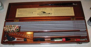
Here is an image of a K&E Leroy lettering set.

K&E Leroy Lettering Set

K&E Leroy Lettering Set

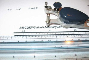
It’s easier to show how it works, than describe it. Here is an image of one set up to make a capital M. The scribe follows the letting in the ruler like jig and ink in the “pen” writes a pretty exact copy of that letter. There are a series of jigs for different sized letters. The scribe tool can be adjust to make the letters slanted in an italic type fashion.

Leroy Letterng Sytems Set Up

Leroy Letterng Sytems Set Up

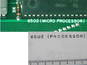
So how do we determine whether this system was used to make the lettering for the Apple 1. The easiest way is to compare the lettering on an actual Apple 1 with an example we know was made with Leroy lettering System.

Apple1 Leroy Lettering

Apple1 Leroy Lettering compared to Apple 1

You can see that the newly created Leroy lettering (bottom) is nearly a perfect match to the Apple 1 (top), so I think that we can be pretty confident that the Apple 1 lettering was made with the Leroy or very similar lettering system.

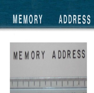
My next question is whether the SCELBI front bezel was also lettered with the Leroy system.

Leroy and SCELBI Front Panel

Leroy and SCELBI Front Panel

Though the lettering is very close, there are some differences in the leg on the “R” and the “A” looks a little different. Also the ends of the strokes on the letters have nice square edges, which would not occur in a Leroy lettered system.

Finally, follow this link to see what Wonder Woman comic books have in common with the Apple 1.

SCELBI TTY interface reproduction PCB – how much interest?

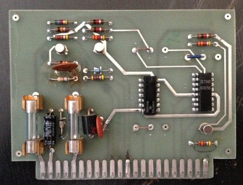
I have the layout for a reproduction SCELBI TTY PCB close to complete. This is essentially a TTL to current loop interface originally designed for interfacing the SCELBI to a Teletype. The board is about 4.5″ x 3.5″ with a connector on a .156 spaced edge for plugging into to an edge connector with solder tail pins. This is very similar to a “Vector” prototyping board. Schematics and a drawing are available on Cam’s SCELBI website.

http://www.scelbi.com/documentation.html

Here is a photo of an original SCELBI TTY interface board.

SCELBI TTY interface

SCELBI TTY interface

I’m not sure how many to make. I’m projecting a bare PCB price at $30 to $40, depending upon interest level. Let me know if you have interest in this board.

regards,
Mike W.

SCELBI Demonstrated at VCFse

I figured I would report on my SCELBI exhibit operations at VCF SE 1.0. I will also cross post this to the new yahoo group, retro-restore.

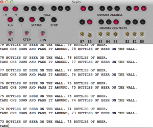
Saturday was dedicated to running the SCELBI calculator program. Toggling in the bootloader before exhibit opening, went without major issues, though I found that focus on toggling was a little hard to keep with numerous other people around getting the facility ready and getting their exhibits ready. No significant problems with downloading and pretty soon I had the program running.

I had left the divide by zero error handler to just halt the CPU. This turned out to be a good way to demonstrate front panel operations, as I just needed to divide by zero in order to halt the cpu. I would then need to toggle in a jump instruction in order to get the program running again. I did have a few issues during the day when the program appeared to stop accepting input. I think the main reason for this, is that the parser is rather particular, expecting only certain characters during input at any given time. Other characters are ignored, making it seem like the program or machine is stuck, when, in fact, the operator is typing the wrong thing. Anyway, the program ran all day, without any need to reload it, until I took it down to demonstrate during my talk.

The second day, I was planning on demonstrating Mark Arnold’s 1K Mandelbrot program. I arrived just 20 minutes before exhibit opening and because I was also demonstrating a Mimeo and had to set that up, and didn’t have time to toggle in the bootloader before opening. I had to do it, while showing off my exhibit. The Mandlebrot program needs to use location zero, so I had to relocate the bootloader. Last time, I did this, I had no issues, but this time my math skills failed me and I spent a considerable amount of time trying to make the Mandlebrot program load right on top of the bootloader. Finally after realizing the error of my ways, I retoggled the bootloader into a better spot and got the Mandlebrot program loaded and running.
If I had been thinking straight, I could have loaded the bootloader into the new location, with the bootloader that was loaded in the wrong place. The SCELBIgenerated Mandlebrot images for the rest of the day, without error.

The bottom line is that the SCELBI ran all weekend, the clock remained stable enough to support RS232 bit-banged I/O without error. The power supply worked great.

A lot of people that had never heard of it, were exposed to the SCELBI for the first time. And finally, I overheard one person say that the reproduction SCELBI was the coolest thing at the show.

Things I would change. I would probably run the Mandlebrot on Saturday, when things were busiest. I also need to find a teletype or current loop terminal,because some people were confused by the Powerbook running a terminal program acting as the terminal.

It was wonderful meeting everyone who came to the show and if you didn’t come I recommend you make an effort to attend a VCF, if you get a chance.

SCELBI Clock – Component Changes for Better Stability

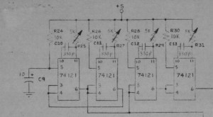
As I noted in a previous post, clock stability on my reproduction SCELBI was pretty bad. The system clock slowed down 10 or 15 percent as the system warmed up. This would have played havoc with my bit banged serial communications, but by the time I was able to toggle in the loader, it would be warmed up and fairly stable.

SCELBI cpu clocks

SCELBI cpu clocks

The timing circuit is made up of 4 interconnected 74121s one shots that control rising and falling edges of 2 interleaved clocks. The timing of each 74121 is controlled by a 5K trimmer resistor and a 300 pF cap. Figuring that the cap was part of the problem, I looked for some NP0 300 pf caps to replace the ones that i was using.

What I found was a modern 330 pF cap, Kemet part # C322C331J2G5TA. While I was at it, I decided to replace the 5K trimmers that I had been using since first bringing up the SCELBI. The original trimmers I bought had the wrong foot print and turned out to be a little jumpy while adjusting. I replaced them with Bournes # 3006P-1-502LF.

Though I don’t know which change made the difference, several trials have shown the new trimmers and NP0 caps seem to have stabilized the clock to the point, where I think I can forget about the “problem”.

The only thing I might do at some point, is try to find some old style NP0 caps to replace the obviously modern Kemet ones.

SCELBI RS232 Interface is put in a Proper Package

update 3/24/14 – I have corrected a mistake in the original posting – TX goes to pin 1, not pin 8 – sorry for an confusion that this might have caused

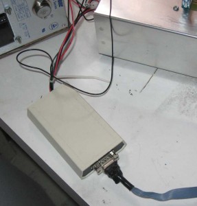
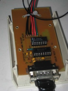
Take a look, it’s a lot cleaner than that bread board implementation that I showed in a previous post. The connections are simple.

  • RX goes to pin 8 of a 86CP11 socket
  • TX go to pin 1 of a different 86CP11 socket
  • Ground goes to pin 11 of the same two 86CP11 sockets
  • Strobe goes to pin 9 of the 86CP11 socket that TX goes to
  • +5V goes to the positive 5 volt power supply terminal
  • SCELBI-RS232
    The enclosure is a Serpac A-20 that I had laying around. The PCB really only needs a 1.5 x 2.5 space to fit, but I had the A-20 enclosure and it makes a nice case for devices that need a DB-9 connector.

    The PCB is single layer, with one jumper wire. This is about as easy as it gets when it comes to etching your own PCBs – single sided and pretty small.

    RS232-SCELBI-PCB

    I etched it using the laser toner method, using glossy paper from a magazine (National Geographic) to make the transfer. The top side legend was done the same way. Put the legend on, after etching and before drilling for best results. I drilled the holes in a drill press with three different drill sizes – #67, 1/32″ and 1/8″. The parts list is pretty basic.

  • 1 2″ x 4″ PCB-??
  • 5 .1 UF capacitors – $.40
  • 1 DB9 connector – $.39
  • 1 MAX 202 chip – $.1.79
  • 1 74LS74 flip flop – $.33
  • 1 Serpac A20 enclosure – $4.56
  • 1 10K 1/4 watt resistor – $.05
  • 1 optional 16 pin socket – $.49
  • 1 optional 14 pin socket – $.45
  • If you have a piece of scrap PCB laying around, like I did, the total cost of parts should be under $10, with over half of that being the enclosure. Actually I had all the parts on hand, and didn’t have to buy anything to build this interface up.

    In the past, I remember marveling when reading magazine and web articles about people building nifty little gadgets with stuff out of their parts box. I would think, how could someone have enough in their stash to do that without buying anything. Well, I guess I’m somehow progressed to the point, where I’ve joined that club.

    Postscript files that can be used to print your own PCB can be found here.

  • http://www.willegal.net/scelbi/SILK1.EPS
  • http://www.willegal.net/scelbi/LAYER1.EPS
  • Where are the schematics? Well there aren’t any. With a single sided PCB, and only a few components, the art for the PCB is enough to use as the schematics. The RS232 interface side was lifted from a TTL to RS232 converter that I did a few years ago. That converter was largely taken from the RS232 portion of my PS/2 to parallel keyboard adapter.