but you’ll have to come to VCFse in few weeks to see it run.
Category Archives: 8008
Power Supply Miscalculation
Quite a few posts ago, I mentioned that I was using bench power supplies to run my SCELBI and that I would update the blog with more information, as I progressed in getting a more suitable, power supply solution. Well, this is the the next post, in what promises to be a series.
What I have done is get a couple of Power-One linear supplies to power the SCELBI. Obviously one needs to be 5 volts and the other at -9 volts. The reason why I selected the Power-One’s is that I know that Nat Wadsworth’s 8B development system used a couple of Power-One supplies.
We know that at the time, a couple of the more experienced SCELBI builders made their own supplies. For instance Circuit Cellar’s Steve Ciarcia made his own for his SCELBI. I’m not that experienced with power supplies or that adventurous. We also know from the price list, that SCELBI Computer Consulting sold supplies. I only know of 1 or 2 of those in existence, and I don’t have details on what is inside the aluminum case, but I’m guessing that there are two Power-One supplies, one for each voltage.
So the only details that we have from back in the time is Nat’s system, and a couple with home brew supplies. We know that Nat used the following Power-One supplies in his system.
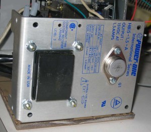
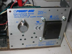
The C5-6 can supply plenty of power for any SCELBI. The B15-1.5 is a 15 volt, 1.5 amp supply. Nat obviously modified the B15-1.5 to supply the -9 volts for his SCELBI 8B.
I did some research and found that Power-One still makes nearly the same supplies. They have been updated a bit to support international mains power, but they are very similar to the ones that Power-One built back in the 70s. Here is a link to the current product specs from Power-One’s website.
http://www.power-one.com/sites/power-one.com/files/documents/power/datasheet/lin.pdf
The C5-6 is now called the HC5-6/OVP-AG. The B15-1.5 is now called the HB15-1.5-AG. Thinking I wanted to recreate Nat’s power supply setup, I did some search and found that these supplies are widely available, but fairly expensive. I also found that numbers of them can be found on ebay, sometimes in older variations and similar models are available from competing vendors, with almost the same model names.
Trying to save some money, I found two NOS units of fairly recent vintage on ebay and purchased them. Both arrived as advertised, in excellent shape in original packaging. I chose to get newer units, since I didn’t want an older unit blowing up my SCELBI
Now my next challenge was to modify the 15 volt unit to supply 9 volts. I’m not going to tell you exactly how I did this, because I don’t want to be sued in case you blow up your SCELBI or yourself or your house. If you don’t know what you are doing, get some help before you do some damage to yourself or your possesions.
I will tell you that I spent the better part of a morning reverse engineering the circuit, making the modifications and testing them. There is a very nice site on hacking on these power supplies, that you should check out, if you are new to this.
http://www.djerickson.com/p1hack/
As part of this process, I calculated the power consumption of the power transistor. The original 15 volt supply had the input to the power transistor at about 26 volts. With a drop to 15 volts at 1.5 amps. This means the power transistor was consuming about (26-15)*1.5 = 16.5 watts. The 2N3055 power transistor is rated to up to 115 watts, though this is under ideal conditions. I figured that running the power supply at 9 volts would increase power consumption to (26-9)*1.5 = 25.5 watts. I figured the power transistor could handle this ok, so I went ahead and made my changes. According to the information I’ve read, the most common failure mode of these power transistors results in essentially a short of the input to the output. This sort of failure will kill almost every IC on your SCELBI, unless the on board fuses blow first, so make sure that you put proper rated fuses on each of the PCBs, as you build your system.
The changes I ended up making involved removing a resistor and adjusting the voltage. I did some basic testing and tweaking and decided I was ready for the next step.
The next step was configuring the two supplies so the B15 supplied -9 and the C5 supplied +5. This was pretty simply done by connecting the B15 supply’s plus output to the C5’s minus output. I put them on the same power switch and powered up. Voltages and everything else looked fine, so I went onto the next step.
At this point, I took one last power check with my existing bench supplies after adding a second SRAM card, which I have just completed building. The 5 volt supply went from 2.2 amps to 2.4 AMPs, meaning each memory card was consuming about .2 AMPs on the 5 volt side. The C5-6 AMP supply was going to be overkill for a full 4K SCELBI, but Power-One’s next smallest supply was only 3 AMPs and this would have been marginal for a full 4K system.
Next, I looked at the bench supply that was suppling -9 volts. It’s meter moved from about .5 amps to .7 amps. This was only an increase of .2 amps, which seemed a little small to me, but since the system was running fine, I didn’t think much about it at the time.
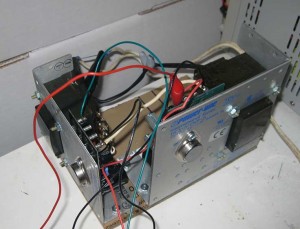
Now I was ready to go, and connected the new supply to my SCELBI. Here is what the setup looked like for my trial. Note that this was for trial purposes only, and as soon as I can, I’ll be doing proper wiring, enclosing it, adding a fuse IEC connector and a switch.
Note that I have kept the transformers as far apart as I could and put them at right angles to minimize interference between them. Also note that the cases of the power transistors carry live voltages, and are not grounded. I’ll have to protect them from accidental shorts or figure a different way to mount these supplies.
I powered up and ran some simple tests on the SCELBI and everything ran perfectly. So what is the miscalculation that I mentioned in the title of this post. Well I did notice that the power transistor on the B15 supply was, pretty warm. Warmer than I would have expected for supplying only .7 AMPs.
Since I had both a new supply and a new memory board, I decided to figure out just how much power this supply was providing. On this supply there is a .22 ohm power resistor that is used for sensing current for the current limiter circuit. By measuring voltage drop over that resistor, with a meter, I could calculate current. Using my old, non precision, Sears meter, I got about a .3 volt drop. Using ohms law, I=V/R, I calculated .3/.22 = 1.5 AMPs. This is substantially more than the bench supply’s meter showed.
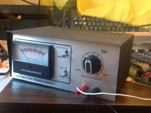
Because of this, I decided to unhook the B15 and do some tests with both my bench supplies. First was the old Radio Shack supply that I was originally using for -9 volts.
It still showed .7 AMPs, however when I measured the voltage, it was only putting out around 6 volts. Clearly the supply was current limited. The interesting thing its that the SCELBI seems to run Ok at this voltage, though I wouldn’t recommend doing it on purpose.
Since this supply is supposed to supply 1 AMP, either the meter was off or the current limiting was kicking in too soon. Putting the new 6 AMP bench supply in place of the old Radio Shack supply showed current consumption of about 1.3 AMPs, close to what I had calculated across the B15 power resistor and way too much for the Radio Shack bench supply. I removed 1 of the SRAM cards and it dropped to .7 AMPs. So each memory card needed about .6 AMPs of -9 volts, way more than the .2 AMPs that the Radio Shack supply showed.
My miscalculation is that Nat’s 8B system with it’s 2102 SRAM and PROM board apparently draws much less power than a 8H with it’s 1101 SRAMs. I should have paid attention to my old power supply post and gotten a beefier Power-One supply to support -9 volts. I guess that sometimes we get so tied up in recreating something, that we don’t pay attention to differences between what we are doing and what someone was doing in the days gone by.
For now, with 2K of memory, the B15-1.5 should be fine, though it runs a bit warm, and I wouldn’t dare run it in an enclosure without fans. In order to grow my system to a full 4K, I think a supply that supports 3 AMPs will be fine. Looking at the Power-One literature, I’m thinking that an HC12-3.4-AG might be the best choice. Stay tuned for more on the SCELBI power suppy saga.
Say Hi At VCFse in the Atlanta Area
This year, for the third year in a row, I’ll be leaving the family in the care of our dog, Toby, and be spending a weekend with fellow retro-computer hobbyists. Since this years VCFeast, had to be cancelled, I’ll be treking down to VCF southeast in Atlanta for the weekend of April 20 and 21st. These weekends are always fun, so I highly encourage everyone that might be interested in these things to make the effort to join us.
Here is the link with informaiton for that event.
http://vintage.org/2013/southeast/
Stop by my exhibit. I’ll be operating a Mimeo 1 and a reproduction SCELBI 8H (one of a very few working SCELBIs in the world). I’ll even give you a chance to “drive”. Tell me you read my blog and get a free SCELBI/8008 reference card.
See you there…
Demo of SCELBI Generating Mandelbrot Images
Most of this video podcast shows me bootstropping the program into the system.
http://www.willegal.net/podcast3-17-13.mp4
One of the reasons I have posted this video is because there are virtually no videos on the web of anyone running an application on a SCELBI.
In case you don’t know about it, the feed for my podcast is at:
feed://www.willegal.net/feed.xml
Now to get cracking on the second 1K SRAM card….
SCELBI 1K Applications Running
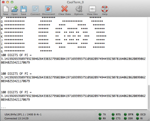
Here is the output of a couple of applications, as captured on a terminal program on a Macintosh connected to my reproduction 8H via a RS232 interface.
The circles on top are part of the output of a concentric circle program that I will write about in a later post. The bottom is the output of a program written by Egan Ford that generates the first 100 digits of the constant PI. This program takes about 21 seconds to run.
Egan has been benchmarking various early 8 bit microprocessors using the generation of 1000 digits of PI as the benchmark. For the 8008, this benchmark needs 4K of memory. Since I only have 1K, at the moment, I asked Egan if he could reduce the scope of the program to fit in 1K. He was kind enough to take on this challenge and this is the result.
The source for the PI program can be found here:http://www.willegal.net/scelbi/pi1k.asm.
The binary, which can be downloaded to your SCELBI with the boot loader discussed in a previous post, is here:http://www.willegal.net/scelbi/pi1k.bin.
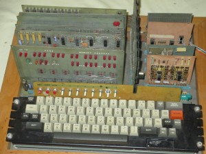
Original SCELBI 8B Surfaces
This is the fourth 8B (B for business) that I have found out about. The original SCELBI was the 8H (for Hobby) and only supports 4K of memory. The 8B supports up to 16K of memory and a 4K PROM card.
The other three 8B’s are:
At the present time, I don’t believe that any of them work perfectly. I know that two of them have SRAM issues, but probably would work if the SRAM issues were resolved.
I’m looking forward to the day in the future, when I can say that I have reproductions of both the 8B and 8H running. However, I need to reproduce 4 additional boards before I can say that I have the 8B running.
As I am pretty busy with the 8H, at the present time, this is going to take some time.
This 8B was built up by the original owner from a bare board set that he purchased from SCELBI Computer. The board in the middle is a TV Typewriter card that was sold by “The Digital Group”. This is the only SCELBI that I know of with a built in video card.
This one is in Dave Larsen’s collection and Dave provided the picture. Information about his collection can be found at http://bugbookmuseum.blogspot.com.
SCELBI/8008 Quick Reference Card
Let me know if you find any issues. Once I get more confidence that there are no mistakes, I’ll get some printed up on card stock.
SCELBI boot loader
One of the challenges of working with the SCELBI 8H, which doesn’t have a built in monitor, is loading software.
To address this, I have written a minimal serial boot loader that can receive serial data and write to memory. It takes a few minutes to toggle in the thirty-seven bytes, but it should save plenty of time, compared to toggling in an entire practical program. In the days of the SCELBI, the most common serial device was a TTY, that could dump data from paper tape at 110 baud using a current loop interface. This loader has it’s timing loops configured to receive 8 bit data at 2400 baud, but some hobbyist may want to retime to run at a TTY’s 110 baud.
This loader will work with a current loop or RS232 interface, depending upon what is connected to the TTL input port 5, bit 8. In my case, I connected a TTL to RS232 dongle that I had built for another task. This dongle is very simple. It consists of a MAX202 chip, some capacitors and some connectors. The other side of the dongle is connected to a modern PC, which can be used as a terminal and a source for dumping data to the SCELBI. Eventually I plan on building reproduction SCELBI current loop boards for those that want to interface to a TTY or other current loop device.
This loader is assembled to run from location zero, but it would be trivial to move it elsewhere.
Here is the listing for the minimal loader.
             INPUT:

000:113         INP INPORT

001:240         NDA          ; check start bit

002:160 000 000 JTS INPUT

005:026 010     LCI 8

            TIMER:           ; 1 1/2 bit times

007:021 DCC

010:110 007 000 JFZ TIMER

013:036 010     LDI 8        ; grab 8 bits

            DATAIN:          ; get 1 bit

015:113         INP INPORT

016:022         RAL          ; move to carry

017:301         LAB          ; fetch current byte

020:032         RAR          ; shift in this bit

021:310         LBA          ; save in B

022:026 003     LCI 3        ; delay 1 bit time

            BITTMR:

024:021         DCC

025:110 024 000 JFZ BITTMR

030:031         DCD          ; 8 bits captured?

031:110 015 000 JFZ DATAIN   ; no, continue

034:371         LMB          ; store byte

035:060         INL          ; increment pointer

036:110 000 000 JFZ INPUT    ; wrap?

041:050         INH          ; increment MSB

042:104 000 000 JMP INPUT   ; continue
Here are the instructions:
In the next few days I’ll put together “put char” and a “get char” routines that will also run over the 2400 baud, 8 bit interface. These will be used as the I/O drivers for downloaded apps, and should be combined with any app that is to be downloaded.
One last thing. The SCELBI is very tolerant of CPU clock speeds, but for this loader to work correctly, the CPU clock has to be very close to 500KHZ. If your recieved data is garbled, there is a good chance your CPU clock is not correct.
SCELBI Base PCB Checkout Complete – If You Were Not Part of the Early Adopter Program, You Can Order Your Board Sets Now
With I/O testing complete, I can’t think of any other tests to run and I declare testing of the 6 SCELBI 8H reproduction PCBs, complete.
The only issue found in this set of boards, is a minor issue with hole size for the Zener diodes as documented here.
With the completion of testing, I’m opening regular ordering at a price of $300 for the six board set. For an extra $35, you can also order a D8008 processor (the 8008 is only available with board set orders).
Please send an email to mike@willegal.net for detailed ordering information. As a bonus, while supplies last, I’ll throw in a scrap, non-functional, backplane PCB that can be used for backplane/chassis mock up work.
Right now I’m limiting sales to 1 SRAM card (1K) per board set, but once I sell a few more board sets, I’ll get another batch of SRAM PCBs made, and open up SRAM PCB sales independant of the board sets.
Card Guide Caution
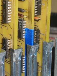
The traces on many of the SCELBI PCBs travel very close to the edge of the board and the card guides. Since the boards do not have a solder mask, it is possible that one of these traces could short out with the metal card guides. Though the card guides are not electrically connected to anywhere else, this potential for accidental shorts should be avoided. After inserting the cards, I carefully checked for shorts. The only card that has a trace actually touching a card guide, is the input card. To prevent accidental shorts I insulated this connection with masking tape, as shown here.
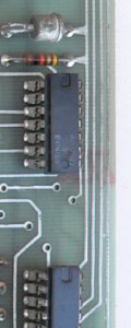
I also checked to make sure that I hadn’t made a mistake in my layout, but the original cards also appear to have this potential issue. See this crop of the image of an original input card from http://www.olson-ndt.com/Scelbi/

