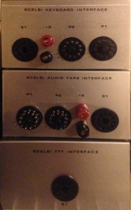
Wiring the Keyboard Interface Enclosure

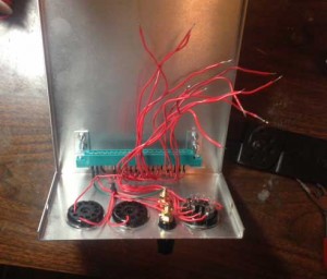
Wiring the Keyboard Enclosure

Wiring the Keyboard Enclosure

At this point, I decided to call it a day and said to myself, my next project isn’t going to involve so much point to point wiring. Counting both chassis, the peripherals and cabling, I must have soldered about 500 point to point wires during the course of the SCELBI project.

By the way, I think the best process for constructing one of these enclosures is as follows.

  • cut and drill the holes
  • add the rub on lettering
  • clear coat the lettering with lacquer
  • add the connectors
  • wire it
  • There are 12 wires left to connect on this chassis.

    For the oscilloscope interface checkout, I think I’m just going to build it up in the chassis, rather than test it and then make the chassis.

    SCELBI – Oscope Digital Board

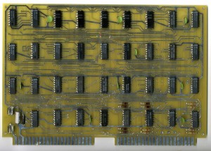
    OSCOPE DIGITAL PCB - front - with rework

    OSCOPE DIGITAL PCB – front – with rework

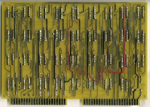
    SCELBI OSCOPE DIGITAL PCB - back - with rework

    OSCOPE DIGITAL PCB – back – with rework

    Notice that I have also recreated the rework. Note that the proper way to cut a trace on a PCB, is to use a sharp hobby knife to make two parallel cuts in the trace an 1/16″ or so apart. Then you remove the small piece of copper between the cuts.

    The Analog board has also been built. What’s left is wiring up the board edge connectors to power and amphenol connectors.

    Scope Analog Power Supply Part II

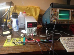
    Before I finalize on values for the SCELBI scope analog supply components, I needed to know how much power the board consumes. To determine this, I set up two bench supplies to power the board and measure current consumption.
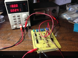
    Scope Analog Board Current Test

    Scope Analog Board Current Test

    Current consumption on both positive and negative rails measures at only about 25 mA. It’s possible current could vary a bit when hooked up to scope output and the digital board for input, but looking at the schematic makes me think that it’s not going to change very much.

    The way this zener based regulator works, is that if the voltage is over 18 volts, the zener shunts current to ground causing a voltage drop over the series resistor. The zener selected has to have enough current sinking capability to shunt the excess current to control the voltage. The resistor has to have enough current capacity to sustain the current for the entire circuit.

    With the 28 volt transformer I found in my stash, the rectified DC voltage with no load is about 22 volts. The formula for finding the amount of current that the series resistor must handle is simply ohms law. Here is the formula for the 150 ohm resistor found on the original power supply.

    I=V/R
    V= 22-18
    R=150
    I= (22-18)/150
    I = 4/150
    I = .026 AMP
    I = 26 mA

    Here’s the tricky part. For a zener to regulate correctly, it must pass a minimum amount of current. The current, the series resistor passes, will be split between the zener and the board. If the board consumes 25 mA, then almost the entire drop of 26 mA over the series resistor is due to the board, not the zener and the zener will only be passing 1 mA. I checked the data sheet of a typical zener, the Fairchild BZX79C18 and it is specified at 5 mA. 1 mA may not be enough to regulate the voltage well, at least for that part. Either a larger input voltage coming from the transformer or smaller series resister will be required, if I was to use a BZX79C18.

    If I switch to a 120 ohm series resistor. The formula looks a little more promising.

    I = (22-18)/120 = .033 AMP
    I = 33 mA

    With the board consuming 25 mA, this leaves 8 mA for the zener to shunt, which should be enough, at least for the BZX79C18.

    I don’t have the specification for the original power supply’s transformer, which may account for the slightly different series resistor value of 150 ohms that is in the original device.

    The wattage capacity of the series resistor and the zener is also important. The formula for watts is simple W = I x V. First for the resistor.

    W = I x V
    W = .033 x 4
    W = .132 watts
    W = 132 mW

    Assuming my other calculations and measurements are correct, even small .25 watt resistors should be sufficient for this application.

    Then for the zener

    I = .033 – .025 (the board consumes .025 Amps, which is not shunted through the zener)
    I = .008
    W = .008 x 18
    W = .144 watts
    W = 144 mW

    The BZX79C18 is rated at 500 mW, so it also should be fine for this application.

    With the low current requirement for this power supply, I’m going to pick up a smaller transformer, as the 1 AMP transformer I had in my parts stash, is clearly overkill and will not fit in the oscilloscope interface enclosure.

    Analog Supply Reverse Engineered.

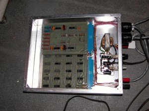
    Thanks to Jack Rubin, I have two pictures of the inside of the only known SCELBI Oscilloscope Display interface. Here is one of them.

    SCELBI Oscope Internal

    SCELBI Oscope Internal

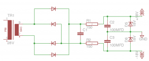
    To me, the surprise was the small power supply located in this chassis. Further research indicates that it was used to power the analog board, which contains 4 SN72741 op amps. The data sheet of these op-amps indicate that they take a +18/-18 volt split power supply. This also can be seen in the SCELBI schematics. Since I had only this and one other picture to go on, at first I wondered whether I could figure out how this supply was constructed. However, it didn’t take too long to come up with the following schematic.

    SCELBI Scope power supply

    SCELBI Scope power supply

    Ignore part numbers in this schematic. The resitors appear to be 150 ohms, probably 1/2 watt. The smoothing caps, C2 and C3 on the +18 and -18 supplies appear to be 100uFD, rated at 10 volts. 10 volts seems to be under rated for an 18 volt supply. I don’t know what value the first smoothing cap C1 is, but it should be rated for around 50 volts. I also don’t know exactly which rectifier diodes, D1-D4 are used. The zenor diodes, D5 and D6 should be 18 volt devices and are used to set the output voltage.

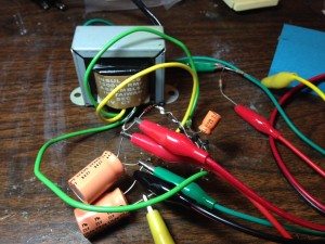
    In order to confirm my schematic, I rigged up a test power supply, using some parts that I had on hand.

    Scope Analog Supply Prototype

    Scope Analog Supply Prototype

    This test jig lacks the zenor diodes, and uses an 28 volt transformer. Output is around +/-20 volts, which should be about right. Next, I’ll have to find some 18 volt zeners and see if I can power the analog board with it.

    SCELBI Oscilloscope PCBs Arrived

    Sometime in 2011, Cameron Cooper planted the idea of reproducing a SCELBI computer into my head. Once he had me convinced, I knew that I wanted to reproduce the entire line of SCELBI computers and I/O peripherals. SCELBI produced 16 different PCBs over the short lived life of their computer line, so this was going to be no small task. I knew that it would take a long time, and I was never sure that I would be able to maintain focus long enough to do them all.

    At last, after 5 years, the last reproduction SCELBI PCBs have been made! Though I still have to build them up, write some software, and test them, the hard and most expensive part of making the PCBs has been done.

    SCELBI Oscope PCBs

    SCELBI Oscope PCBs


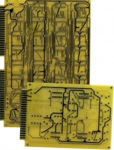
    The digital board is the big one and the analog board is the small one. The digital board takes 16 bits of input from the computer for each character and coverts it into 4 bit digital X and Y vectors and the blanking information that make up a single character. The analog board coverts the XY vectors into analog voltages suitable for oscilloscope input. The analog card also will control horizontal and vertical positioning of each succeeding character and line.

    I still have some parts to acquire, but I should have the missing parts and be able to begin assembly in about a week or two. Meanwhile, I can do some work on the software.

    Here is the list of all 16 SCELBI PCBs
    Main System Cards
    1100 CPU – 8H/8B
    1101 Data bus buffer – 8H/8B
    1102 Input – 8H/8B
    1103 Backplane – 8H
    1104 Front Panel – 8H/8B
    1105 1K SRAM – 8H
    1106 Memory Expansion – 8B
    1107 4K SRAM – 8B
    1108 Backplane – 8B
    1109 PROM – 8B

    Peripheral Cards
    2100 Oscilloscope digital
    2101 Oscilloscope analog
    2102 Audio Tape output
    2103 Audio Tape read
    2104 Teletype interface
    2105 Keyboard

    SCELBI Keyboard Interface Checkout

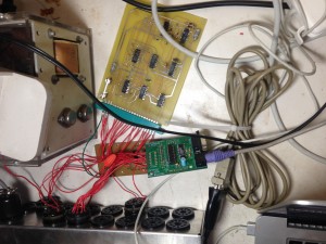
    After bench testing, I had to write an 8008 driver and hook up the keyboard interface to a real SCELBI to complete checkout. The standard I/O ports for the keyboard are port 4 for input and port 16 for output. For testing purposes, here is how the setup was hooked up.

    Keyboard Interface Checkout

    Keyboard Interface Checkout

    Here is the driver.

    167 ; HERE IS THE USER DEFINED CHARACTER INPUT TO READ FROM KEYBOARD INTERFACE
    168 ;
    169 ; returns character in A
    170 INPUT:
    171 44-256 111 INP KEYIN ; read keyboard
    172 44-257 240 NDA ; is a new character present
    173 44-260 120 256 044 JFS INPUT
    174 44-263 125 OUT KEYOUT ; ack character read
    175 44-264 044 177 NDI 177 ; clear MSB
    176 44-266 007 RET ; return character in A with MSB clear

    In order to test, I simply changed the input driver on my modified creed monitor (MCMON), moved it to SRAM address 010-000 and downloaded using the MCMON monitor that is in EPROM on my SCELBI 8H. Then I jumped to the downloaded monitor to see if it would take input from my PS/2 keyboard adapter instead of the serial port. It all worked exactly as expected. I just need to put it into an enclosure and I can consider the hardware for this board done.

    The software will probably take some more work, as I will have to integrate this keyboard driver with the oscilloscope driver for MEA, once I get the oscilloscope cards built. Speaking of the oscilloscope cards, I think I should be ordering the PCBs within a week or two. That interface will take considerably more software in order to get it working.

    SCELBI Keyboard Interface Basic Checkout

    SCELBI Keyboard Interface Checkout

    SCELBI Keyboard Interface Checkout

    This setup is being used to checkout basic functionality of the SCELBI Keyboard Interface card. The card was designed to interface to a Don Lancaster Keyboard as described in a couple of articles published in Radio-Electronics in 1973. The first article was the February issue and contained instructions on building a basic non-encoded keyboard. The April issue contained a follow on article with a description on how to build a keyboard encoder. These links contain the original articles and are hosted on Michael Holley’s comprehensive SWTPC pages. This keyboard/encoder design does not latch keypresses, but simply outputs what it sees, as the keystrokes occur. The strobe is supposed to come after the keyboard data, and end prior to keyboard data, so interfacing hardware doesn’t have to do anything fancy to latch the data.

    The SCELBI keyboard interface accepts 8 bits of input data from the keyboard, with the most significant bit (MSB) being a strobe. The interface to the SCELBI computer contains 8 bits of data, with the MSB being a data available indicator. The data available indicator is cleared by a single input (high to clear) from the computer. The data and strobe coming from the keyboard can be independently inverted or not, by correct selection of jumpers around Z1 and Z4 and inclusion of the Z1 and Z4 7404 inverters or not. Leaving the 7404s out and bypassing them with jumpers will result in inverted data. With my PS/2 keyboard adapter, I needed to use the 7404 to keep the interface from inverting data. At one time, I had a version of PS/2 adapter firmware that would invert data, which would have been handy in this case, but I removed that feature some time ago.

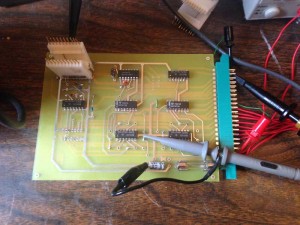
    It appears that SCELBI engineers had trouble using the Radio-Electronics keyboard strobe to latch data correctly. The strobe is OR’d with the data bits in order to make up an internal strobe for use within the board. Many keyboard designs internally latched data, and this extra circuitry doesn’t work since the incoming data never goes away, and the strobe stays stuck on. For my testing, I used one of my PS/2 adapters. I considered two solutions to this problem with strobe. My first thought was to modify my PS/2 keyboard adapter firmware to make it emulate a non-latching keyboard. In the end, after playing around with the interface, I decided to simply delete the gates that OR’d keyboard data with strobe. This can be seen in the following photo as the deletion of IC Z7 and the jumper from the pad at pin 2 to the pad at pin 12.

    Configured Keyboard Interface

    Configured Keyboard Interface

    With this simple modification, I have bench tested the keyboard interface to the extent possible. Next, I need to write a small 8008 keyboard driver and connect to my reproduction SCELBI 8H.

    Source of Sn72741 op-amps

    The SCELBI cassette and oscilloscope interfaces both use a rather unusual variation of the jelly bean 741 op-amp. This is the TI SN72741, which puts this op-amp in a 14 pin DIP package. Though they can be had on e-bay, I recently discovered that expediters.com has them for $5.50 each. They can be found at this link:http://www.expediters.com/index.jsp?path=product&part=845153&ds=dept&process=search&qdx=0&text=Sn72741

    SCELBI Power Supply Internals

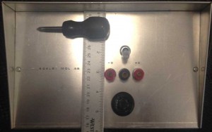
    This SCELBI 8B power supply is built in a shadow box type chassis that is approximately 10″x5″x6″.

    SCELBI-8B-power-supply-front

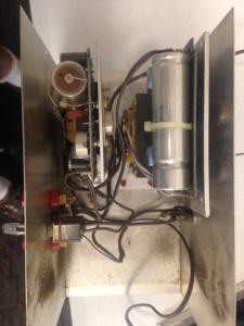
    The internals are simply two Power-One linear Supplies, a switch, a fuse, 3 binding post type connectors, an amphenol 78S4 type connector and a fan. Here is an image of the interior. The fan is connected to the top, so isn’t visible in this view. The 5 volt supply is a C5-6 and the -9 is a modified B15-1.5. Be aware that the -9 supply is not powerful enough for a fully loaded 8H chassis.

    SCELBI Power Supply Internals

    SCELBI Power Supply Internals