Great Mimeo Kit News – Kits available soon

PCBS

The batch of boards I purchased last month were all sold as bare boards, so I’m getting a new batch made up. More than half of those boards went to a company in Los Angeles which turned them into non-functional props for the new Steve Jobs movie starring Aston Kutcher. I’m expecting that that movie will feature some cool looking props, when it comes out.

Anyway the new batch of PCBs will take a couple of weeks to arrive.

Kits

I’m excited to announce that there will be some changes for those of you that wish to purchase Mimeo kits. I’ll be selling boards to you and parts kits will be purchased directly from Unicorn Electronics. I’ve sent BOM information to Rob at Unicorn, who is working hard to get all the required parts. Rob tells me that he has most parts on hand, already, but there are a few more to gather. I am really excited about this arrangement, as it should greatly increase the availability of Mimeo’s to the vintage computer hobbyist and free up time for me to work on new projects – a win for everyone. People wanting to build kits would have to take a couple of extra steps to get their kits. I think that this is a small price to pay for increased availability.

Mimeo Assembly Manuals
For hard copy assembly manuals, I’ll probably make it a separate, extra cost option, though I’m also considering using a print on demand service, so you would have to order the manual separately.

Assembled Mimeos
For those of you who want a built up Mimeo, I’m looking into building a few complete systems, with keyboard, enclosure and cassette player. Be forewarned, this sort of system will take a lot of time and money to put together. I haven’t set a price, but the number I have in mind will put it into the luxury item category.

Apple II rev 0 PCBS?
Ordering and putting together kits for Mimeo has been a huge time sink, and this change will allow me more time to work on new projects. If it works out well, I’ll also seriously consider making a new run of Apple II rev 0, reproduction motherboards. Unicorn would become the default parts supplier for that kit, as well.

Simpler Kits
For simpler kits, like the ACI, PS/2 adapter and Brainboard, I will continue to supply the complete kit, just like before.

First Lot of Super Proto Boards on order

First, a little background.

About a month ago, Rich Dreher tipped me off to an EEPROM issue he had seen in the past when interfacing an EEPROM to the Apple II bus. Well I didn’t have any issues with my prototype unit, but decided to do some additional testing with different EEPROMs. Back in the lab this EEPROM testing got confused with a flakey motherboard issue and the whole thing set me back a month.

After moving to a different motherboard, I eventually figured out that ATMEL EEPROMs don’t play well with the Apple II address bus, just like Rich indicated. However, an alternate source, XICOR, makes EEPROMs that do seem to behave quite well, so I’m back on track. During initial bringup, I had done my original testing with XICOR, which is why I didn’t see the problem with ATMEL parts.

So besides checking out EEPROM behavior, I made some design tweaks, checked out bus timing, made sure interrupts work and so on. At this point everything looks good,so I just pulled the trigger on a small trial run of boards. With any luck I may even manage to get some sent out to those of you HW hackers that are visiting K-Fest.

I plan on completely documenting this board including the GAL online, so little to no printed documentation will be created. If I can figure out how to do it, I want to set up a wiki type documentation environment where prototypers can add their own designs and share their knowledge with everyone else.

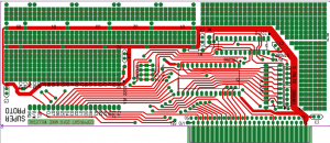
Here is the top side layout:

Super Proto Rev 0

Super Proto Rev 0

The base feature set includes

  • Onboard 32K EEPROM – only 2K is normally addressable from Apple’s C800-CEFF and CX00-CXFF I/O space
  • EEPROM is programmable directly from the Apple II’s 6502.
  • Glue logic integrated in 22V10 GAL – replaces a number of 74LS glue chips that are commonly seen in designs like the super serial card and the mockingboard
  • Data bus fully buffered with 74LS245
  • PCB location for 6522A VIA, with no additional glue logic required
  • Two general purpose proto areas
  • Locations for more than 5 300 mill DIP chips of varying pin count
  • With 6522 VIA, room for an additional 40 pin dip package. This does cut into 300 mill DIP area. but it should be possible build a 3 channel Mockingboard on the super proto board.
  • Synthesized psuedo PH2 clock available – was required for 6522 inteface
  • The hope is that this board takes care of all the heavy lifting of interfacing to the Apple II bus and lets you focus on the the fun side of hardware hacking on the Apple II.

    Pricing hasn’t been set, but it will be well under $100 for a kit. Bare boards will also be available.

    Stay tuned.

    Interesting Brain Board remote switch

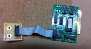
    Corey Cohen came up with this easy method of creating a remote switch panel for the Brain Board. Here is an image of his prototype version. Knowing Corey, I’m sure that his final version will be mounted on a nice plexi panel.

    Brain Board Remote Switch Thingy

    Brain Board Remote Switch Thingy

    One DPDT switch controls which bank on the brain board is selected. Corey has loaded integer basic and the original monitor onto his second bank. The other SPST switch controls whether brain board or motherboard roms are selected after reset – this second switch is essentially the same as the firmware board toggle switch.

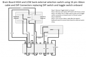
    One wire needs to be added to the back of brain board to connect Apples reset to the DIP socket at pin 2. Reset can be picked up from the onboard switch location. It is the center of the three holes.

    A ribbon cable is used to connect the remote switch box to the Brain Board. As you long as you stay within reason, longer ribbon cables than pictured should pose no issues. The only active signal is reset, which, when asserted, is held low for relatively long periods of time.

    Brain Board Remote Switch Setup

    Brain Board Remote Switch Setup

    Howard Cantin interview – Woz’s reaction

    See my earlier post describing my interview with Howard Cantin.

    I sent the excerpts of this interview to Woz to get his impressions. Woz was happy to see the interview and responded with some interesting comments. My email is indented and in gray, Woz’s response is not. This is published in my blog with Woz’s permission.

    On Apr 17, 2012, at 9:27 AM, mwillega wrote:

    Hi Steve,

    A couple of weeks ago I had a telephone conversation with Howard Cantin. Howard is known as the PCB layout person on the Apple 1. Apparently he was also involved in the first Apple 2 layout. A few of the things he said, are quite different than what I have heard and read elsewhere. I’d be interested to know what you thought of what Howard told me.

    My comments below.

    THANK YOU THANK YOU THANK YOU. It’s rare to find the true stories from back then.

    What follows are taken from notes taken during the call with Howard. The call was not recorded, so words are mine.

    Background
    Howard worked from his house for clients including Atari and Apple. Howard says he laid out all the boards for the first four years at Atari, until Nolan Bushnel sold the business. He also laid out first boards of other electronics startups in valley that became major players. Though he couldn’t remember the names of others, he says he did the first PCB for Intel. Howard says he was well connected to insiders in the valley electronics community and was the person to go to, when a PCB layout was needed. Howard related how he set many of the standards in PCB layout that were followed by others.

    Nolan Bushnell of Atari was often in a hurry and pushed Howard to hurry along a design. Howard says he was a fast designer, partly because of working under the pressure provided by Nolan. He could add a chip to a layout in hour.

    Steve Wozniak
    Regarding Steve Wozinak, Howard related to me, the often retold story about how Woz created a game design that used 60 parts instead of the 100 in the design that preceded it. Howard related that engineers at Atari couldn’t understand the design. Because they couldn’t understand it, Atari ended up not using it.

    How Howard Worked
    Most designs had an edge connector, so he would start with that and then add parts that connected to the edge connector. Then he would connect those parts to the parts that connected to those parts and so on. Vias were expensive and to be avoided, and would take up the space need for 3 traces. Howard provided his original artwork and photographic transparencies ready for the PCB manufacturer to his clients. Howard often didn’t negotiate price before taking on a job, but a typical cost was 6 to 8 dollars per chip. Howard worked directly from customers schematics, and is still proud of his ability to produce a result that matched the schematic perfectly.

    The Hobby Computer
    The first board that Howard did for Jobs and Wozniak was a computer to be sold to the hobbyists at the local computer club. Howard says that this computer was the board that provided the financing to start Apple Computer. Howard refers to this as a hobby computer, not an Apple Computer. Howard says the two Steve’s always were together and they conducted their discussions with him together. To pay for this computer, the Steve’s tried to trade an old Fiat Station Wagon for services rendered. Howard asked for cash, so the Fiat was sold and proceeds used to pay Howard. As some point, stock was offered, but this was also refused.

    The First Apple Computer
    Steve Jobs appeared to be a perfectionist to Howard. During the layout of the first Apple Computer, Howard had three proposed layouts with different form factors. There apparently was a lot of back and forth figuring out the form factor. Finally, Howard suggested one of the layouts happened to exactly match the size of a piece of legal paper (8.5×14) and Jobs selected that one. The proto area in the corner of this computer was empty and it was Howard’s idea to put pads for a chip and an array of pads that became the proto area.

    Though Howard did the main chip placement on this second layout, Howard paid a woman to lay the tape for traces. She was not very good and the traces she laid were not very straight. Jobs wasn’t satisfied and took the design and had it redone digitally. Jobs later told Howard that this re-layout cost Apple three months. Howard asked Steve why he needed to redo the layout and Steve said he was only going to do it once in his life.

    Howard did not use that woman for laying traces again. Howard told me that after that project, that he would have refused more work from Apple. In any case, Apple didn’t come back to him.

    PIRACY
    Howard also mentioned that he thought that the one of the Steve’s took a picture of an Atari board that he happened to be working on as the same time he was working for them. He thought that the Steve’s might have used this picture to duplicate an Atari design in some way. Howard did not have any specific details about what exactly was done with the image. Howard also said he talked on the phone with someone in England that might have been investigating another pirated Atari design. At one point, Nolan Bushnel asked Howard to pirate another design, but Howard refused. Howard now thinks that this was Nolan’s way of checking Howard’s honesty.

    Anyway I have these comments about what Howard said. I’d be interested in what feedback you had.

    He is confused about the “Hobby” computer that was the Apple 1 and the “first Apple Computer” that was the Apple II.

    When we met Howard at his home in Scotts Valley (I believe that’s where) we had not yet come up with the name Apple.

    Howard’s story says the vehicle sold to finance the Apple 1 was a Fiat Station Wagon, not a Volkswagon bus.

    It could be. It was some vehicle that really wasn’t being used as I recall. All I know is that I sold my most valuable possession, my HP-65 calculator, to come up with my half. Steve and I always did everything in business 50/50 (with regard to money).

    Do you remember taking the Apple II layout that was done by Howard’s subcontractor and then reworking it in a digital format?

    This does match my recollection, although the steps and reasoning for the switch to computer layout I wasn’t close enough to. I saw it being done but I don’t recall a negative reasoning, just that computer layout was ‘better’.

    Finally, his story of Steve Jobs and you somehow stealing an image of a Atari PCB and making some kind of profit from it. He was very vague about exactly what was done. That part of Howard’s story seems incredibly unlikely to me, especially given the inconsistantcies with the rest of the story.

    I would never do such a thing. I never photographed any Atari board nor remember it being done while I was around, but it’s possible that Steve Jobs did photograph one at some other time. I’m against stealing designs. Look at my designs, for example. You won’t find a bit of them extracted from some other design or data sheet. Check out almost every other hobby computer design around then and that’s all they were, duplicates of Intel data sheets. My design was always so original that it’s partly why Atari couldn’t understand it (Breakout).

    This story rings incredibly true and accurate, which is unusual in our business. Obviously it’s first hand from Howard and not filtered through communications types in companies or the media.

    Thank you for letting me know I’m not going crazy with all the things others have reported on these matters.

    — Woz

    Thanks and best regards,
    Mike W.

    Continue reading

    Convert a Virtual II “tape” to load into a real Apple II

    If you use the program Virtual II, you may know that it reads and writes to a virtual tape. Files written by Virtual II can be easily moved to an iPod and read on real Apple IIs. Here is the process I use.

    1) Save the “tape” to a file using Virtual II’s normal tape saving process. This file is in AIF format, but volume probably needs to be increased in order to be read by a real Apple II from an Ipod type music player.

    2) Rename the file to a .aif suffix from the .cass that Virtual II normally uses.

    3) Covert the AIFF file to 16bit 41.1 kHz sampling rate and size. This can easily be done by loading the file into Quicktime PRO and using the export command to convert it.

    4) Now the AIF file can be dragged into a GarageBand track. Add 6dB volume to the track and optionally cut out any unnecessary silence at the beginning of the recording.

    5) Finally export to itunes and sync to your ipod.

    6) Play back to your Apple II at maximum volume and you should be able to read your Virtual II generated tape.

    The same process can be used to generate audio files for the Apple 1, using the Wozanium Pack ROM image loaded into Virtual II. However, you may not need to increase volume for real Apple 1’s or clones as they don’t seem to need as much volume as the Apple II.

    Prototype Protoboard working

    I use a GAL to reduce part count in this design. I’ve had a terrible time programming the GAL with a vintage Data I/O 29B and finally gave up and bought a cheap chinese programmer that seems to work better.

    Prototype Prototype with LED on

    After a few tweaks, especially surrounding the difficult timing on the 6522 VIA, I have the prototype up and running and even blinking a LED. I found an Apple tech note about interfacing to the 6522 that I decided to follow exactly. I had one other issue with handling the release of the selection of the C800-CFFF ram space. Some of the schematics I found online, use some inverters and a cap to slow down response to releasing the selection, presumably to ignore glitches. I found that using the same delayed clock to condition this signal as is used by the 6522 interface, seems to work as well.

    I implemented the PROM on this device with an EEPROM and I have been able to write some small test programs and save them in EEPROM without any need for a prom programmer. I think experimenters are going to love this feature. I wish I had done this on the Brain Board, but I didn’t think of it at the time.

    For Apple 1 lovers, note that I did a quick checkout in a Brain Board/Wozanium environment this morning and had no issues.

    I have lots of ideas for projects and it will be easy to connect it to a solderless breadboard for quck and easy prototyping. Besides use for experienced hackers, I want to make this a tool for people who want to learn fundamentals of computer interfacing and hope I can find time to do a series of introductory projects. What it ends up doing, besides blinking a LED, and the projects I come up with, is up to the creative people in the Apple II community.

    I’ll definitely bring the prototype to TCF east next month. I’ll have to figure out how much more testing is required before ordering a batch of boards. I’ll definitely try it in my IIe, but what else I run it in remains to be seen. The PCB layout has been tracking changes made in the prototype, so once I decide I have a good final design, it will not take long to get the boards made.

    MM5740 to AVR pinout mapping

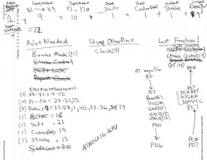
    In the PDF at the end of this post, I have captured some notes associated with an abandoned project to use an ATMEL AVR – ATMEGA16 in place of a National MM5740 keyboard decoder. Both parts come in 40 pin DIP packages, which makes the AVR substitution idea work pretty well.

    avr encoder

    avr encoder


    The initial idea was to check to see if the AVR could be used as a plug in replacement, with some socket stacking and rewiring. I was also considering building a Datantetics Apple 1 and Apple 2 compatible keyboard using Cherry key switches and an AVR as the encoder. The reason why I stopped this project is that costs would probably have forced a selling price of close to $200. These notes are associated only with mapping the pinouts. I had assumed that if I could make a reasonable mapping that the software would be pretty straight forward.

    It turns out that there are just enough pins to do the job without any loss in functionality. The strobe control, Output enable (OE) and shift lock functions are not used on Apple II/IIplus or earlier Datantetics keyboards. The Bounce Mask function can be accomplished in the AVR’s software. The clock of the AVR can be generated by either the internal RC oscillator or an external crystal input.

    The PDF follows:
    MM5740-to-AVR-mapping

    A Conversation with PCB designer Howard Cantin

    We live in an unique age where important people engaged in the early days of the personal electronics industry are often accessible and willing to talk about the “old days”. Today I had the good fortune to have a telephone conversation with Howard Catin. Howard is the PCB (printed circuit board) layout designer responsible for early Atari and Apple PCBs. I was interested in talking to Howard because of my reproductions of his work have created a large amount of curiosity about how the original PCBs were created. I was also interested in his relationship to Steve Jobs and Steve Wozniak.

    At that time, PCBs were laid out on a transparent film on drafting boards. Tape and preprinted images of each ICs footprint were transferred to the film in order to make the image of the board. The film was photographed and the photographic films of each layer were provided to the PCB manufacturer in order to fabricate the actual PCBs.

    What follows are taken from notes taken during the call with Howard. The call was not recorded, so words are mine. Footnotes, denoted by brackets are additional information that Howard did not relate, but add context to the story.

    Background
    Howard worked from his house for clients including Atari and Apple. Howard says he laid out all the boards for the first four years at Atari, until Nolan Bushnel sold the business [1]. He also laid out first boards of other electronics startups in valley that became major players. Though he couldn’t remember the names of others, he says he did the first PCB for Intel. Howard says he was well connected to insiders in the valley electronics community and was the person to go to, when a PCB layout was needed. Howard related how he set many of the standards in PCB layout that were followed by others.

    Nolan Bushnell of Atari was often in a hurry and pushed Howard to hurry along a design. Howard says he was a fast designer, partly because of working under the pressure provided by Nolan. He could add a chip to a layout in hour.

    Steve Wozniak
    Regarding Steve Wozinak, Howard related to me, the often retold story about how Woz created a game design that used 60 parts instead of the 100 in the design that preceded it [2]. Howard related that engineers at Atari couldn’t understand the design. Because they couldn’t understand it, Atari ended up not using it.

    How Howard Worked
    Most designs had an edge connector, so he would start with that and then add parts that connected to the edge connector. Then he would connect those parts to the parts that connected to those parts and so on. Vias were expensive and to be avoided, and would take up the space need for 3 traces. Howard provided his original artwork and photographic transparencies ready for the PCB manufacturer to his clients. Howard often didn’t negotiate price before taking on a job, but a typical cost was 6 to 8 dollars per chip. Howard worked directly from customers schematics, and is still proud of his ability to produce a result that matched the schematic perfectly.

    The Hobby Computer
    The first board that Howard did for Jobs and Wozniak was a computer to be sold to the hobbyists at the local computer club [3]. Howard says that this computer was the board that provided the financing to start Apple Computer. Howard refers to this as a hobby computer, not an Apple Computer. [4]. Howard says the two Steve’s always were together and they conducted their discussions with him together. To pay for this computer, the Steve’s tried to trade an old Fiat Station Wagon for services rendered [5]. Howard asked for cash, so the Fiat was sold and proceeds used to pay Howard. As some point, stock was offered, but this was also refused.

    The First Apple Computer
    Steve Jobs appeared to be a perfectionist to Howard. During the layout of the first Apple Computer [6], Howard had three proposed layouts with different form factors. There apparently was a lot of back and forth figuring out the form factor. Finally, Howard suggested one of the layouts happened to exactly match the size of a piece of legal paper (8.5×14) and Jobs selected that one [7]. The proto area in the corner of this computer was empty and it was Howard’s idea to put pads for a chip and an array of pads that became the proto area.

    Though Howard did the main chip placement on this second layout, Howard paid a woman to lay the tape for traces. She was not very good and the traces she laid were not very straight. Jobs wasn’t satisfied and took the design and had it redone digitally. Jobs later told Howard that this re-layout cost Apple three months [8]. Howard asked Steve why he needed to redo the layout and Steve said he was only going to do it once in his life.

    Howard did not use that woman for laying traces again. Howard told me that after that project, that he would have refused more work from Apple. In any case, Apple didn’t come back to him.

    PIRACY
    Howard also mentioned that he thought that the one of the Steve’s took a picture of an Atari board that he happened to be working on as the same time he was working for them. He thought that the Steve’s might have used this picture to duplicate an Atari design in some way. Howard did not have any specific details about what exactly was done with the image. Howard also said he talked on the phone with someone in England that might have been investigating another pirated Atari design. At one point, Nolan Bushnel asked Howard to pirate another design, but Howard refused. Howard now thinks that this was Nolan’s way of checking Howard’s honesty.

    [1] Atari was sold to Warner Communciations in 1976
    [2] This must be the Breakout game
    [3] Homebrew Computer Club
    [4] In my opinion, this computer is actually the Apple 1
    [5] Is this the source for the often heard van story?
    [6] Actually the Apple 2
    [7] I often wondered if the size of an Apple 2 matching a legal page size was a coincidence
    [8] Though the Apple 1 layout is very consistent, I could tell that the Apple 2 layout is quite a bit more consistant – now I know why

    A2 proto board update

    After an email exchange with Vince Briel where Vince casually indicated that the A2 community really needs a prototyping board, I’ve decided to raise priority and get a batch of these prototype cards built.

    I’m a little concerned about timing, especially with the 6522. The Mockingbird board, which also uses the 6522, does some strange stuff with clock timing and I need to really investigate what is going on with a real board. So, before doing the production build, I need to get a prototype proto board working.

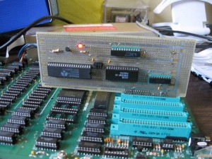
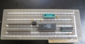
    Normally, I would just etch a prototype PCB at home, but a proto card needs a bunch of holes drilled in it which would take a long time to do manually and besides, I might need to make some significant changes, which is easy to do with wirewrap. In addition I had on hand an Apple Hobbyboard, which is ideal for this project. The Hobbyboard had been used before for a simple temperature sensor project that I did in the 80’s, but the old circuit had been removed from the board a few years ago. So in the last week, I have wirewrapped the new circuit onto the old Hobbyboard.

    prototype proto board

    prototype proto board

    I haven’t gone very far in debugging because I keep frying the 16V8 GAL chips I’m using to cut down on chip count (and leave more prototyping space). Could be something to do with the ancient Data I/O Pal programmer I”m using. Anyway, there is real progress being made on this project and I hope to get things squared away so I can make a build this spring or summer.