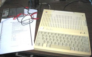
Which Apple Interpreted Basic is the Fastest?

While at the vintage computer festival, I had an Apple 1, an Apple II with integer BASIC and an Apple IIplus with Applesoft all up and running.

At one point late in the afternoon on Sunday, I decided to have a simple performance contest between these machines. This is the program.

10 FOR I = 0 TO 10000
20 NEXT I
30 PRINT “DONE”
40 END

Two machines were matched against each other and the program started at the same time on both machines. The first to finish was the winner.

After several heats, here are the results.

1st place – Apple 1 – by a little
2nd place- Apple II
3rd place – Apple II plus – way behind

At first, I was confused by the Apple 1 beating the Apple II, as the Apple II should run about 5% faster than an Apple 1. This is do to the more efficient method for refreshing memory on the Apple II. The Apple 1 stops processor clocks while refreshing, while the Apple II uses unused portions of the 6502 bus cycles to refresh memory (and read video display data). Integer BASIC on the Apple II is a direct development of Apple 1 Basic, so I was thinking that the performance would depend on the processor, not the Integer BASIC implementation, which were basically the same.

After a while I realized that Apple 1 BASIC might be a little simpler than Apple II BASIC and thus faster. I ran a second test. In this test, I booted the A2plus that I had there at the show into Apple 1 mode, with the Brain Board/WOZANIUM and ran the test against the original Apple 1. Both machines were now running virtually the same version of BASIC. In this case, the Apple II beat the Apple 1 by the expected amount. Thus, Apple 1 BASIC running on an Apple II, is the fastest version of Apple BASIC.

However, keep in mind that if print statements are added to the loop, the Apple II will beat the Apple 1 by a substantial amount.

VCF – great time for a vintage computer nut

Last weekend was VCF east 7.0. I spent the weekend among other vintage computer nuts. It was a great time, and I highly recommend going out of your way to spend the weekend, next time this event is held. This event can not be fully appreciated unless you take the time to listen to the lectures, and see the museums that comprise the info-age facility.

Among the highlights was seeing part of an Apollo Guidance Computer, something I studied last year. I was thinking of doing some kind of recreation at one point.

Apollo Guidance Computer

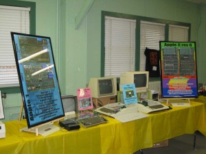
Here is my exhibit, where I showed the Mimeo, A2 rev 0, brain board and PS/2 keyboard adapter. My exhibit won the gold medal in the preservation/recreation catagory.

my VCF east 7.0 exhibit

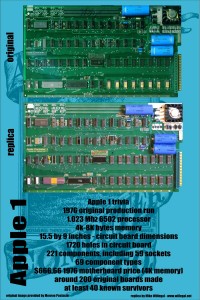
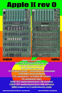
Here are the posters I displayed in my exhibit.

First the Apple 1/Mimeo poster

A1 poster

A1 poster

Second the Apple II/rev 0 poster

A2 poster

A2 poster

Note on BB assembly, Version 5.1 PROMs shipped, and Why Is the BB Upside Down?

For people that still had the FCS, 4.0 PROMs, version 5.1 PROMs were shipped on Monday and should be in your mailboxes soon. I will only be updating version 5.0 PROMs upon request. The only difference between version 5.1 PROMs and 5.0 PROMs, is in the power up screen and it doesn’t affect operation in any way.

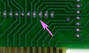
Though assembly is really straight forward, there is one thing to watch out for when assembling Brain Boards. Where the traces run between pads, the soldermask reveal extends right up to the edges of the traces and, on some boards, where registration isn’t perfect, the solder mask reveal may expose a tiny part of the trace. There is potential here for shorting the trace to the pad when soldering a component to this pad.

Brainboard-soldermask

When soldering these pads, be careful that you don’t accidentally bridge the gap between the pads and the adjacent trace. If you can’t get rid of the bridge with a solder wick or solder sucker, the easy fix is to cut the solder bridge with a hobby knife. Check continuity with an ohm meter to make sure the connection is broken.

Is the Brain Board Designed Upside Down?

It’s funny that no one has questioned or commented about the upside down layout on the brain board. This was done on purpose because of the vastly improved layout possible with upside down chips. The layout of the address and data bus connections between the 27c256 and 74LS244 sockets and the edge connector would be much more complicated if the chips were right side up. Flipping the 27c256 right side up moves the data bus connections of the 27c256 to the opposite side of the chip from the 74LS244 and Apple data bus. Also, all the lower address lines would have to be crossed to properly connect the 27C256 to the Apple bus.

Once I flipped the 27C256, I figured I had to flip all the chips and the silk screen to prevent confusion and mistakes during assembly.

Version 5.1 Brain Board Manual posted on BB page

The only difference between version 5.0 and 5.1 is the power up screen. The original A1 had alternating “_” and “@” signs with the @ signs flashing. The @ signs actually disappeared during the flash off.

With version 5.0, I had the @ signs flashing between normal and inverse instead of completely disappearing. With version 5.1, this was fixed to have the @ signs disappear during flashing, like on the original Apple 1. I actually had it right on earlier versions, but made a change to dramatically improve initialization time in version 5.0 and created this discrepancy at that time.

I’ve been shipping 5.1 since 4/1/11, and have heard no reports of issues. In fact, other than the flashing @ signs, I haven’t heard of issues with any of the versions, other than someone verifying the memory corruption bug with 4.0, that I previously reported in my blog.

Because the difference is pretty small and does not affect operation in any way, I don’t intend on automatically shipping updated 5.1 PROMS to those who already have 5.0 PROMs. If you have version 5.0 you can request an update or if you have a PROM burner, I can send you an Intel hex file with the new image.

There are still a few people with version 4.0 that I owe an update to – I plan on shipping version 5.1 to you around the end of the month.

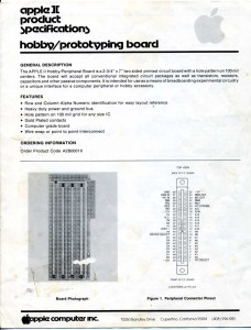
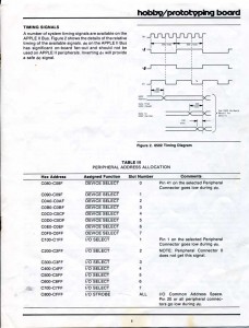
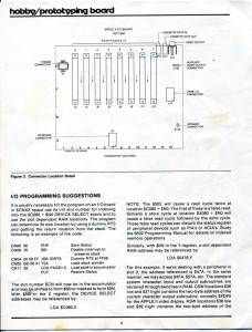
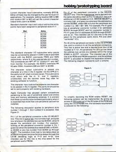
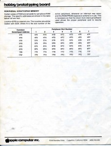
A2 Hobby/Proto Board Evolution

This PCB layout is now in it’s fifth major revision and counting. Here is how it’s evolved.
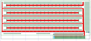
A2 Hobbyboard Layout


1) A direct copy of Apple’s Hobbyboard. Many years ago, I used one of these cards to build an A/D interface with temperature sensor. This layout is ideal for prototyping with wire-wrap technology, but not so good for point to point wiring, which I prefer these days. So I moved on.
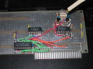
A2 Shutter Tester on QRC proto board

A2 Shutter Tester on QRC proto board

2) A direct copy of a Quality Resarch Company (QRC) Apple 2 computer prototype board. I used one of these a few years ago to build a prototype shutter tester. This board is ideal for point to point wiring, but I have decided it would be neat to build into the layout some basic I/O components like space for a 2K PROM and data bus transceivers.
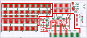
The first proto design of my own making

The first proto design of my own making

3) This led to the first of my own designs. I incorporated space for a bus transceiver, a 27C256 EPROM, a SPDT switch and a DB 9 connector in this one. I used the 27C256 instead of a 27C16 because they are easier to find and cheaper, despite the fact that it has 16 times as much memory than is really needed. However, the handing of the I/O strobe for the 2K memory exansion space is kind of messy. On Apple’s super serial card, it takes 4 74LSXX series chips. This would require a lot of wiring and take up a big piece of the proto area. For these reasons, I decided to put this logic in a PAL or GAL and include the wiring right on the proto board, which leads to my next design.
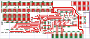
My Second Proto Design

My Second Proto Design

4) In this version, I removed the toggle switch, thinking that it was not really that useful an idea. I was thinking I wanted the capability of interfacing an AVR micro-controller, while some other folks thought that a design that supported classic chip would be more appropriate. The 6522 VIA is a classic 6502 family part and includes some neat features including built in timers. I also switched from using a 27C256 to 28C256 flash part, so that it could be programmed in place, without the need for a PROM programmer. All along, I’ve wanted the capability of supporting that AVR on this board, but supporting both a micro-controller and a VIA seemed kind of awkward on the same layout.
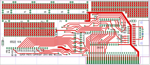
Third Proto Design

Third Proto Design

5) My current layout tweaks the previous by making the half of the 6522 that is used for input/output pins a little more generic. The 6522 will still drop right in, but if something different is desired, then you just need to connect the bus interface to the proto area the way you want it. It is fortunate that the 6522 was set up with the I/O ports on one side of the chip and the bus interface on the other. In some ways, the 6522 VIA bus interface is just about an ideal generic A2 interface device. You have the system clock, the device select signal, read/write, interrupt, the data bus, and the four address lines that will address all 16 locations in the device select region of each slot. If you need some other bus signal, it can always be picked up off of the pads near the edge connector. One of my next challenges is to see if I can interface an AVR micro-controller directly to this bus, without additional components.

This design is not done evolving, but at this point, I think I’m happy with most of the major design decisions. I have plenty of FLASH memory for the program, a 6522 VIA for hardware interfacing and DB-9 for connection to the external world. With the 6522 in place, I have space for 4 16 pin chips, an 8 pin chip and plenty of discrete components. Yet the 6522 could easily be replaced by something else, like the AVR I keep thinking about.

One thing that might change is the DB-9, which takes up a lot of real estate. A KK type header like the one used on the super serial card is likely to replace it.

If you have ideas or opinions on this hobbycard design be sure to let me know. The more input I get, the better this card is likely to become.

Rising Ebay Prices for Apple II Systems

I’ve noticed a trend in rising prices for A2 systems on ebay. I usually buy parts machines when I need a new system or components for a project. In the past, I’ve been able to get parts A2 plus systems (often with a lot of extras) for around $50 plus shipping.

Within the last week an A2 (not plus) system listed as parts or repair went for $810! Granted, this system had a few desirable components – but still…

An A2 plus system also listed as parts or repair went for $183.49!

Also, I’ve seen several A2 plus systems go for close to $300 lately. These were not parts systems, but it’s not long ago when that was the expected price for a non-plus system.

Is this a temporary situation, or is the day of the dirt cheap, $50 A2 plus parts system, behind us?

At least IIe’s are still dirt cheap.

Apple IIc – first impressions

THE BACKGROUND:

I’ve had Apple computers since I bought my Apple II in the first half of 1978. Within a year I had a job as a programmer for Systems Enginering Laboratories, and my interest in personal computers dissipated significantly. In early 1984, my home computer was upgraded to a 128K mac with imagewriter. Since then, I’ve been using macs as my primary personal machines.

It was only in 2004, when I pulled my original Apple II down from that attic in order to make a shutter tester, that I became interested again in the original Apple II line. Because my computer interests moved in other directions, I had little experience with the Apple II line since about 1980. Until recently, I never had any particular interest in the Apple IIc. It seems that it might be useful as a portable machine, especially since so many modern TVs have composite video inputs.

Well a few months ago, I was given a IIc without power supply. Since then, I’ve been very busy with the Brain Board and Mimeo 1 work and haven’t had time to cobble the power supply together. Well this morning I found a few hours and finally was able to bring this baby up.

First challenge was the power supply. Apple specs 1.2 AMPs DC at 15 volts. I have a Radio Shack (realistic) bench power supply rated at 1 AMP, with variable output, up to 25 volts, DC. I figured that since the power supply could be turned up to 25 volts that maybe it would source the 1.2 AMPs at 15 volts. After wiring the connector, I connected it up. The computer made a beep but then shut itself down. After several attempts, I realized the power supply couldn’t hack it and was shutting itself down. OK, now I’m looking for a wall wart with something close to the correct parameters. The first one that looked close, was rated at 1.2 AMPs at 12 volts DC. Now this same wall wart wasn’t hefty enough for the DISK II-USB project, so I was skeptical, but decided to give it try. I hooked it up with a voltmeter on the DC outputs so I could see how much the voltage sagged when the disk drive was turned on. To my surprise, this wall wart seemed to be able to handle the IIc, at least without anything external plugged in. It did sag down to around 11 volts at times, but I think the internal power supply will accept anything down to 9 volts. Ok, so now I have an Apple IIc powered up, what are my initial impressions.

Apple IIc test set up

THE REVIEW:

  • First of all, the IIc’s disk drive is quieter than what I’m used to. It’s not silent, but certainly much quieter than the old Disk IIs.
  • The keyboard really isn’t that good. Maybe mine is old and out of shape but the keys seem clunky to me.
  • I run a lot of old integer basic programs and use firmware cards instead of language cards in my II and II plus machines. This isn’t really a knock on the IIc, I just have to make sure I boot with a disk that has integer basic on the drive. Same problem exists with the IIe, which is pretty much the same machine, only with slots.
  • It would have been nice, if they could have squeezed one expansion slot into this form factor.
  • For some Brain Board compatibility tests, I had to open up the machine to borrow the 65C02 processor. Though it is not hard to get into, there are some rather fragile tabs that help hold the case together. Be careful, if you decide to open this unit up.
  • I haven’t checked composite video compatibility with any digital monitors, but I’ll have to check that out before I actually try taking it somewhere.
  • Summary…Other than the clunky keyboard, I think that this is a cool machine and I may actually end up dragging it along on a trip in the future.

    Brain Board Update #2 – Beta Almost Complete

    The Brain Board/Wozanium pack web page is up and includes a link to the Beta Manual with has all kinds of information about the implementation. I have a little more to add, including an example downloadable driver that allows a user to control the machine through a super serial card.

    I have had some good feedback from the Beta team. Several improvements have been made to the Wozanium firmware and will undergo testing this week. I plan on starting general shipments on 3/21/2011.

    Cost for kits will be $59 with free shipping in USA and $10 shipping internationally. I also plan on offering built up units, once I get through any flurry of initial kit orders. Send me an email, if you have any questions.