Disk II interface update #10

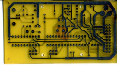
I have all the parts and etched the board this morning. Registration between layers isn’t as good as I’d like, but it will do for a prototype. It will take another evening to drill holes and solder in the components. Some of you may wonder why I go through the effort of making a PCB for a prototype. Well I think a PCB results in a vastly more presentable finished board and I like the esthetics of it. The result should also be a little more reliable than the results of other prototype processes. I don’t think that it is that much more trouble than say wirewrap or point to point prototyping. Finally, creating a prototype using the same artwork that a production house would use, makes going for a production run much less risky.

The board is designed to fit an a Serpac A20 enclosure, as used on my shutter tester project – http://www.willegal.net/light/tester.JPG. This is not the cheapest enclosure, but I think it is a pretty good looking off the shelf box. I’ll have to come up with some kind of cool decal to put on top of it.

-Mike W.

PS In this image I haven’t yet removed the ink from the laser printer image that is used to form the resist.diskii-PCB
Disk II interface update #9

Quick update. i’ve got board lay out complete and parts on order for the second proto board. I may start the etching process today. This promises to be one of the most tricky two sided boards that I have tried to etch at home. When etching boards at home I try to keep them to a one sided design, but connecting the 20 pin header basically is forcing a two sided design. Also starting to work out interface/Disk II protocol. It looks like ADT will be used as a starting point for the interface.

New Replica Parts Arrived

I just received a IIplus with an extra keyboard. I will be refurbishing the case, at least one of the keyboards and checking out the power supply in order to offer them for sale in conjunction with rev 0 replica kits.

Once checked out, I’ll remove the “out of stock” status for Applesoft ROMs and the case/power supply and key board components on my kit builders page.

Depending upon how bad the keyboards are, I may part one out and have key switches for sale on my garage sale page again. I am currently out of spares.

Disk II interface update #8

Quick update. Next proto board is starting to shape up. It makes use of two AVRs. An attiny2313 running AVR-USB firmware to support the USB interface. This is connected to a atmega88 running my DISK ][ RWTS firmware via a serial interface. The USB will start with a CDC (communications device class) type device, though I could potentially change this without changing the hardware.

I probably have another couple of weeks to finish the layout, get the parts I need and build the board

Disk II interface update #7

With a tweaked RC oscillator calibration setting, the UART is behaving and I can format a disk that can be completely copied by an Apple ][. Read performance seems to be around 1 soft error in 1000 sectors read. This is about 1 soft error in 2.7*10^6 bits. I’m not sure what is expected with one of these old drives using old media, but I’m declaring success (at least for now).

I’m running out of things to work on with this first proto board.

I need to start working on proto ][ with more memory, USB interface and an improved low drop out voltage regulator. I’m likely to switch to a crystal based oscillator since the built in RC oscillator calibration setting seems too course for this application. Seems like there is only 1 calibration value that works reliably. and I’d like a little more precise clock.

Disk II interface update #6

I’ve mostly recovered from the power supply disaster. Instead of replacing the ATMEL AVRISP programmer, I purchased a USBtinyAVR kit. I figured that I would be able to repair any damage instead of doing a replacement, if I burned another programmer up. Well the kit works alright, but isn’t nearly as well integrated into AVR studio software as the ATMEL programmer was. Anyway, I’ve been able to get back to work finishing the format and write functions, well sort of.

Now I am working with a regulated bench power supply jumpered to the mother board with alligator clips (I guess I don’t learn). The wall wart is on the back burner until I can find a better 12 volt regulator solution.

Since the great power supply disaster I have had issues with dropping RS-232 characters being sent from my proto-board. I also found that I couldn’t fit all 16 sectors on a track during the format process. Tweaking the speed of the drive solved the formatting issue, but this clearly isn’t an acceptable workaround. What is really happening with both these issues is that, for some reason, the processor clock is now running way too slow. I need to recalibrate the internal RC oscillator that I’m using to clock this device. That will hopefully solve both issues.

Disk II interface update #5

Ok, I’ve done some additional analysis of the power supply, while waiting for the new flash programming device to show up. Here is the situation. The power draw is between .25 and .75 AMPs depending upon whether the motors are running or not. The LM7812 voltage regulator can supply enough power, but it has a specified drop out of about 2 volts. Therefore I need a .75 AMP at 14 volts, DC, in order to supply enough power for this application. The wall wart I was using is rated for 1 AMP at 12 volts. It couldn’t support the .75 AMP at 14 volts. I’ve been looking for a higher power wall wart. I did find a 15 volt 1 AMP surplus unit at http://www.primelec.com for only 2.95 that might work. However after thinking about it, I think it would be better if I could lower requirements a bit. This would allow me to find a more common source for power, such as a 13.8 volt DC supply meant to replace a car battery. I have one of these at home, and it’s not quite up to the job, due to the large 2 volt dropout with the LM7812, even though it is rated at 2.5 amps. In order to solve this, I’m going to investigate low drop out 12V DC regulators. An example might be the LM2940 from National, that reduces the dropout to .5 volt typical or 1 volt maximum. I found another example implementation on the web that used op-amps controlling a FET. The dropout on this design is far less: .1 volt, but it requires a few more parts.

http://www.drbob.net/project/powersupply/linear/12v1alvdfxd/default.html

This is kind of interesting to me, since I’ve had some fun with op-amps in the past.

Now that I know overall power consumption, I also plan to power the 7805, 5 volt regulator off of the 12 volt regulator, instead of unregulated input power. This should lower the power consumption (and heat output) of the 7805.

Disk II interface update #4

Well I confirmed that I have a power supply issue. I’m seeing a nearly 2 volt drop in the 12 volt supply when stepping. The onboard regulators are doing their job, but the wall wart I’m using doesn’t appear to be able to deal with the instantaneous load of the stepper motor. I’ve confirmed this by connecting a bench power supply with alligator clips and seeing a much more stable 12 volt supply during head movement operations. Unfortunately in the process, I somehow fried my AVR flash programmer. Until I build or buy a new one, further debugging will be delayed. I will be able to work on designing the USB interface while I sort out the flash programming issue, though.

Disk II interface update #3

Format is having issues, when moving between tracks. The first sector written after moving to next track isn’t reliably readable. A rewrite of the track, always works. I’m going to have to review my power supply, as I’m guessing that I’m not providing enough juice to cleanly power the stepper motors. This is something I’ve suspected before, but haven’t taken the time to fully investigate. Now appears to be a good time, since it is getting in the way of finishing the format function.