Apple IIe Fast Scroll Routine

I’ve been working on improving my Apple IIe TTY emulation application. One of the major limitations with it, is the amount of time it takes to scroll the Apple IIe’s screen, especially when in 80 column mode. In order to improve this function, I wrote my own fast scroll routine. Kind of interesting how close it turned out to a comment I received to a previous post, even though I forgot about that comment by the time I did this.

;
; Fast Screen Scroll Routine
;
LINE1 EQU $400
LINE2 EQU $480
LINE3 EQU $500
LINE4 EQU $580
LINE5 EQU $600
LINE6 EQU $680
LINE7 EQU $700
LINE8 EQU $780
LINE9 EQU $428
LINE10 EQU $4A8
LINE11 EQU $528
LINE12 EQU $5A8
LINE13 EQU $628
LINE14 EQU $6A8
LINE15 EQU $728
LINE16 EQU $7A8
LINE17 EQU $450
LINE18 EQU $4D0
LINE19 EQU $550
LINE20 EQU $5D0
LINE21 EQU $650
LINE22 EQU $6D0
LINE23 EQU $750
LINE24 EQU $7D0

FAST_SCROLL
  STA STORE80 ; enable aux mem
  STA PAGE2OF ; page 1 first
  JSR FS_DOIT
  STA PAGE2ON ; now do aux mem

FS_DOIT:
  LDX #39
FS_L1:
  LDA LINE2,X
  STA LINE1,X
  LDA LINE3,X
  STA LINE2,X
  LDA LINE4,X
  STA LINE3,X
  LDA LINE5,X
  STA LINE4,X
  LDA LINE6,X
  STA LINE5,X
  LDA LINE7,X
  STA LINE6,X
  LDA LINE8,X
  STA LINE7,X
  LDA LINE9,X
  STA LINE8,X
  LDA LINE10,X
  STA LINE9,X
  LDA LINE11,X
  STA LINE10,X
  LDA LINE12,X
  STA LINE11,X
  LDA LINE13,X
  STA LINE12,X
  DEX
  BPL FS_L1

  LDX #39
FS_L13:
  LDA LINE14,X
  STA LINE13,X
  LDA LINE15,X
  STA LINE14,X
  LDA LINE16,X
  STA LINE15,X
  LDA LINE17,X
  STA LINE16,X
  LDA LINE18,X
  STA LINE17,X
  LDA LINE19,X
  STA LINE18,X
  LDA LINE20,X
  STA LINE19,X
  LDA LINE21,X
  STA LINE20,X
  LDA LINE22,X
  STA LINE21,X
  LDA LINE23,X
  STA LINE22,X
  LDA LINE24,X
  STA LINE23,X
  LDA #$A0 ; clear last line
  STA LINE24,X
  DEX
  BPL FS_L13

  RTS

This routine takes about 18 milliseconds to run on a 1 MHz Apple IIe, compared to the standard monitor scroll routine which takes 34 milliseconds. Other than unrolling the loops, which would greatly expand the size of the function for a minimal speed increase, I think this is about as fast as it’s going to get.

18 milliseconds is still not fast enough for my TTY emulation package, so I’m going to have split it up into several segments and check for input events between segments. However, now that I have my own version of the scroll code, I’ll be able to split it up relatively easily.

There are some other issues with the standard monitor COUT routines for this TTY application, so it’s very possible that I’ll end up customizing all the COUT routines. For instance, I’ve already customized the “BELL” function for performance reasons. The Carriage Return function also had to be customized, because on a teletype, CR does not force a line feed.

An Apple with a Very Interesting History

My web site doesn’t draw the number of hits that many more popular sites do, but my site occasionally attracts some emails that turn into very interesting stories. The discovery of John Draper’s Apple II is one of them, and I need to put together a few more posts in order to describe his system and it’s history. However, right on the heels of the discovery of Draper’s Apple II, another very interesting system has just surfaced which is housed in this enclosure.

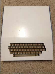
Apple Case

Apple Case

The story is that it was taken out of Steve Jobs office by Apple employee and manufacturing engineer, Don Hutmacher, after Steve was fired in the mid 80s. The story goes that Don was allowed by his boss to go into Steve Job’s office take anything that was left over. It had been picked clean by the time that he got there. He noticed this computer and a bag of Starbucks coffee, and that is how he ended up with it.

More to come…

Amazing Discovery

In a previous post, I mentioned that an amazing vintage find has just been made. Last week, I received an email with this picture.

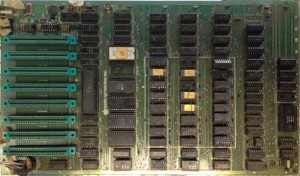
Apple II rev 0

Apple II rev 0

The person said, “Hi mike. I found your page via Google. Can you help me identify this apple product please? I think it is an apple ii board. ”

I receive these sorts of requests from time to time and this request for information is typical. My answer went like this:”It’s a revision 0 Apple II motherboard. You don’t find many with original 4K memory jumper blocks still installed. Almost all of them were upgraded to use 16K memory chips. Looks like someone has done some unconventional memory upgrades, but it otherwise looks pretty original. It could be a really early one, the serial number is usually written in sharpie in the white block near the power supply connector. There may be some masking tape over it.”

After a few more email exchanges that day, the person sent me an email declaring that he thought it was “Charley”. Charley is the machine that John Draper, “Captain Crunch” turned into the first phone freak computer. This machine was seized during a police raid at a housewarming party, held on 22nd of October, 1977. Here is a link to a copy of the party invitation.

There is always the danger of fraud in cases like this, but I’m pretty well convinced that this is actually “Charley”, and I’ll explain more in a future post.

Dr. Galfo’s Integer BASIC Compiler

I just put up a web page with documentation and DSK images of Dr Galfo’s Integer BASIC Compiler (IBC). This compiler was used in development of some well known Apple II games. It runs around six times faster than WOZ’s BASIC interpreter, so it’s worth trying out. Compiling an Integer BASIC program is easy. You simply load the program in the standard Apple interpreter and then run the compiler. You will be prompted for a few options and then, after the compiler is run, are given the option of running the program.

Radio Teletype Explored – part 1

Before I acquired Chris Galfo’s HAM software package for the Apple II, I had already developed a simple RTTY (Radio Teletype) setup that used my Apple IIe as a terminal. This series of posts will go over what I did to put together this setup. Before going into details of each component, I’ll go over the general setup and a few of the decisions that lead to the choice of major components.

In the beginning, my goal was to set up a RTTY station using 70’s era components. As you will see, I went a little into the 80’s in the choice of some specific components, but the basic platforms on which those components were based, were all available in the 70’s.

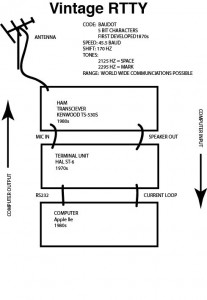
RTTY Block Diagram

RTTY Block Diagram

As you can see, my setup is made up of 4 main components.

  • The antenna – I’m currently using a simple inverted V dipole because of ease of deployment and low cost
  • The radio – Kenwood TS-530S – I chose this unit as it is an vintage unit that is an evolved version of a Kenwood TS-520. The TS-520 was released about the same time as the SCELBI-8H, but my TS-530S was sold in the early 80s. I chose the TS-530S over the TS-520 primarily because of it’s integrated digital frequency display and support for additional bands
  • The TU (teminal unit) – HAL ST-6 – The main job of the terminal unit is to convert tones coming from the radio audio output to a series of 1s and 0s which is digital information that can be interpreted by a computer or teletype. It also can convert 1s and 0s coming from a teletype or computer to tones to be sent to a radio’s microphone input for transmission. The HAL ST-6 was released about 1970 and still has a reputation as being one of the best terminal units around
  • The keyboard and display unit – Apple IIe – I choose this over the SCELBI because of the integrated video display and keyboard. I chose the IIe over earlier Apple II models, because it has an integrated 80 column display. Teletypes have 72 column output, which would require 2 lines to display on a standard 40 column Apple II display. I explored using a straight Apple II with a plug in 80 column card, but found some differences between the 80 column support in an Apple IIe and the standard Videx 80 column card. Turns out the differences were significant for this application, so I went with the Apple IIe
  • VCF east, Apple Monitor II Problem Explored

    My setup at VCF east X had three monitors/CRTs setup as displays. They run all day, starting at about 9:00 AM, until the exhibit closes. One of them was an Apple Monitor II.

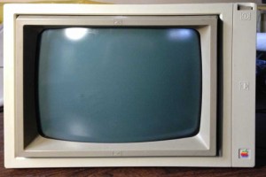
    Apple Monitor II

    Apple Monitor II


    Saturday, towards the end of the day, I noticed that the Monitor II wasn’t displaying anything and the “power” light wasn’t lit. Doing a quick check of power cords and trying a power cycle got no response. Since I was so busy, I decided to put it aside and remove one of the less important systems from my exhibit.

    During day on Sunday, I casually asked Ian Primus, who is a CRT repair guru, if he knew of any common problems with the Apple Monitor II. He said that they never fail, but he’d be glad to take a look, later on. Late in the afternoon on Sunday, when activity was dying down, I decided to open it up and see if anything was obviously wrong. Once I got it open, Ian and Jeff Golas who was in the next “booth”, did a 5 minute investigation. They found that the fuse was blown, but little else obviously wrong. There was no obviously blown caps. Ian checked the rectifier diodes and a couple of power transistors, but they all checked out. Jeff measured the power consumption by using his meter as a jumper over the blown fuse, and it came out at .4 amps. Jeff said that he had a similar problem with one of his Apple Monitor II’s. It also blew the fuse. However his unit only measured .2 AMPS. With the quick inspection over, I closed it back up and decided to do a complete inspection when I got home.

    I found some time Thursday night and took it apart for a complete inspection. After carefully making sure the tube was discharged, I disconnected the connectors going to the main logic board so I could pull it out enough to get to the back of the PCB. I set up my home-brew ESR tester and checked all the caps and could find no fault. I did find one located next to the horizontal output transistor heat sink that was a bit brown. However, it checked out fine, just like all the others. I also used my diode checker to check all the diodes and transistors on the board. I could find no fault with any of them.

    After a few hours of probing, I was coming up with nothing, all the components that I could test, looked good. The next day, I stopped at a local shop to see if they had a replacement for the cap that was slightly brown, but they didn’t have the correct value. I decided that since it tested good, that I would leave it alone. I decided to clean the tarnished pins on the CRT yolk, reassemble and repeat the power test that Jeff had executed at VCF east. This time, the power consumption was down to .2 AMPs. I’m not sure why it dropped in half, maybe some connector wasn’t making good contact. Since the monitor is rated at 30 watts, .2 AMPs seems like normal power draw and matches what Jeff measured on his unit.

    At this point, I was at a loss and decided to replace the 500 milliamp fuse and operate the monitor for a while. I figured that if there was something seriously wrong, the fuse would go again, or perhaps a marginal part would fail completely. I put everything back together and ran the unit for about an hour and it performed as designed.

    I’m not sure if it’s fully repaired. I did find a SAMs repair manual for the unit online, which showed details of signals on the logic board, but since it’s working so well, I decided not to pursue evaluating all the signals in minute detail. For now, I just plan to keep a close eye on it whenever I am using it.

    First of my “Vintage Digital Radio” Webpages is Up

    This is the first of several webpages that I plan on putting up to document my efforts to integrate vintage computer operation with present day HAM activities. It is not currently linked to from my main homepage or other vintage web pages.

    This page provides access to one of the first commercial HAM communications packages to be released anywhere. During my explorations of HAM integration with early vintage computers, I ran across several references to a software program released by a CH Galfo. Though I couldn’t find any actual images of the software or documentation, I was lucky enough to make contact with Dr Galfo, himself. Better yet, he was friendly and willing to help make the software accessible to vintage computer people. He sent me a floppy and a hard copy of the documentation, both of which I’ve been able to copy into a web friendly format. Dr Galfo indicated that since there is no commercial value, that you should feel free to copy and distribute.

    http://www.willegal.net/digitalradio/Galfo-HAM-App.html

    6502 memory test gotcha – 6502 cheat sheet error

    One of the more popular programs that I’ve written is this 6502 memory test. One person using this test to checkout his Mimeo, recently discovered that it doesn’t work with his early white 6502. Turns out that that particular 6502 is a nice collectors piece, without a functioning ROR instruction. I used the ROR instruction at the end of the third test, so the program hangs when run on an early 6502 with the missing ROR functionality.

    ;
    ;
    ; all test 2 passes complete – prepase for test 3
    ;
    LDA #$7F
    BNE NX_TEST ;always branch

    CHK_TEST3 ;floating zeros in progress or done
    CPY #3
    BNE CHK_TEST4
    ;
    ; pass of test 3 complete – 8 passes in all with 0 in each bit position
    ;
    SEC
    ROR TEST_PATRN ; rotate right – Carry to MSB, LSB to Carry
    BCS NX_PASS2 ; keep going until zero bit reaches carry

    I haven’t checked it, but I think the following code will accomplish the same basic test without using the ROR instruction.

    ;
    ;
    ; all test 2 passes complete – prepase for test 3
    ;
    LDA #$FE
    BNE NX_TEST ;always branch

    CHK_TEST3 ;floating zeros in progress or done
    CPY #3
    BNE CHK_TEST4
    ;
    ; pass of test 3 complete – 8 passes in all with 0 in each bit position
    ;
    SEC
    ROL TEST_PATRN ; rotate left – MSB TO Carry, LSB = Carry
    BCS NX_PASS2 ; keep going until zero bit reaches carry

    I recently discovered that my 6502 cheat sheet has an egregious error. The ROL and ROR instructions move the Carry bit into the LSB and MSB (respectively), not the MSB and LSB. In other words the instructions are rotate through carry instructions.

    I’m not sure how I managed to mess this one up or why it took so long for me to notice this or why no one else noticed it. Perhaps the functionality of these instructions are so well known that most people don’t need to refer to a cheat sheet to understand functionality. Clearly, I knew how they worked (or were supposed to work in the case of the early chips) when I wrote the 6502 memory test.

    Brain Boards Sold Out – summary of pending projects

    I built and tested the last two kits over the holiday break and sold them on eBay. I made 59 PCBs, and kept 1 for myself, so there are 58 that were sold, either as kits or fully assembled.

    Once the initial interest passed, they were very slow sellers, so I’m not expecting to make any more. I have some ideas for an enhanced version, but that is very far down my list of things to do, so I don’t know if or when I’ll take the time to work on that.

    Here are just a few projects on my backlog that are ahead of the enhanced Brain Board. These will easily keep me busy for a couple of years or more.

  • Finishing all the SCELBI I/O Boards
  • Getting Apple II RTTY on the air – reception is working – transmission software is coded, but needs lab testing prior to actual “on air” tests
  • Getting vintage computer Morse code encoder/decoder on the air – Jack Rubin sent me an early Byte Magazine article with a 8008 software package for this, so I’ll probably do this on the SCELBI
  • Fabricating SCELBI Chassis Components
  • Putting together the VCF East 10 display and “Fix It” lecture
  • Hack together a Mimeo with 20K DRAM
  • Move Apple II RTTY application to the Mimeo/Apple 1
  • I have identified another board that is rare, of historical significance and worthy of replication
  • I have other ideas, that are even further out, such as doing a Mark-8. If I did a Mark-8, I would probably etch my own boards. This would probably be pretty easy to do, as the artwork was published and there was no solder mask and the holes were not plated through. I don’t think I would make batches of boards for sale, as this has been done already, and some of the parts are in the harder to find category.

    I also really need to do a manual/book on the SCELBI and I have made some half hearted attempts to start this. The main obstacle is that I’d want to scan and OCR the original docs and that is a very laborious process.