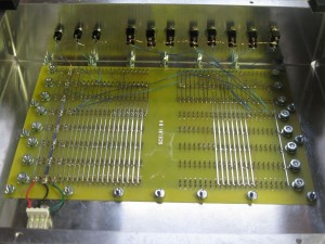
Following instructions in the manual, I wired the front panel switches. I also added a temporary jack for power, until I get something more authentic.
With this setup, once I complete the memory and input boards, I should be able to toggle in a tiny program. Actually I may be able to toggle some instructions directly into the CPU, even without the memory card.
The push button switches should be normally off, with one terminal connected to ground and the other to the control signal. Pull up resistors on the CPU board keep the signal high, until grounded. The toggle switches are connected in a similar fashion. Connect the center terminal to either ground or the data bus input signal and the other to the terminal such that when the switch is in the “up” position, pull up resistors on the input board keep the signal high. When the switch is in the “down” position, the signal should be connected to ground.


Mike, Good stuff.
Looking at my backplane PCB I couldn’t tell which side was the component side. Question Answered!
J