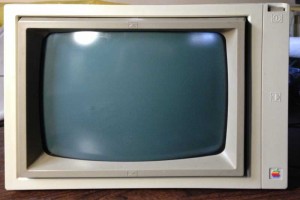
My setup at VCF east X had three monitors/CRTs setup as displays. They run all day, starting at about 9:00 AM, until the exhibit closes. One of them was an Apple Monitor II.
Saturday, towards the end of the day, I noticed that the Monitor II wasn’t displaying anything and the “power” light wasn’t lit. Doing a quick check of power cords and trying a power cycle got no response. Since I was so busy, I decided to put it aside and remove one of the less important systems from my exhibit.
During day on Sunday, I casually asked Ian Primus, who is a CRT repair guru, if he knew of any common problems with the Apple Monitor II. He said that they never fail, but he’d be glad to take a look, later on. Late in the afternoon on Sunday, when activity was dying down, I decided to open it up and see if anything was obviously wrong. Once I got it open, Ian and Jeff Golas who was in the next “booth”, did a 5 minute investigation. They found that the fuse was blown, but little else obviously wrong. There was no obviously blown caps. Ian checked the rectifier diodes and a couple of power transistors, but they all checked out. Jeff measured the power consumption by using his meter as a jumper over the blown fuse, and it came out at .4 amps. Jeff said that he had a similar problem with one of his Apple Monitor II’s. It also blew the fuse. However his unit only measured .2 AMPS. With the quick inspection over, I closed it back up and decided to do a complete inspection when I got home.
I found some time Thursday night and took it apart for a complete inspection. After carefully making sure the tube was discharged, I disconnected the connectors going to the main logic board so I could pull it out enough to get to the back of the PCB. I set up my home-brew ESR tester and checked all the caps and could find no fault. I did find one located next to the horizontal output transistor heat sink that was a bit brown. However, it checked out fine, just like all the others. I also used my diode checker to check all the diodes and transistors on the board. I could find no fault with any of them.
After a few hours of probing, I was coming up with nothing, all the components that I could test, looked good. The next day, I stopped at a local shop to see if they had a replacement for the cap that was slightly brown, but they didn’t have the correct value. I decided that since it tested good, that I would leave it alone. I decided to clean the tarnished pins on the CRT yolk, reassemble and repeat the power test that Jeff had executed at VCF east. This time, the power consumption was down to .2 AMPs. I’m not sure why it dropped in half, maybe some connector wasn’t making good contact. Since the monitor is rated at 30 watts, .2 AMPs seems like normal power draw and matches what Jeff measured on his unit.
At this point, I was at a loss and decided to replace the 500 milliamp fuse and operate the monitor for a while. I figured that if there was something seriously wrong, the fuse would go again, or perhaps a marginal part would fail completely. I put everything back together and ran the unit for about an hour and it performed as designed.
I’m not sure if it’s fully repaired. I did find a SAMs repair manual for the unit online, which showed details of signals on the logic board, but since it’s working so well, I decided not to pursue evaluating all the signals in minute detail. For now, I just plan to keep a close eye on it whenever I am using it.


If you were running higher current than expected (due to dirty contacts) but still within the fuse’s limit, the fuse may have just gone open due to thermal fatigue. Did it have the “splattered” look of a high current short or was the fuse wire broken or dangling?
The fuse certainly didn’t have that splattered look. The high current/fatigued fuse theory certainly is something that I have considered. I’m a little bit skeptical that cleaning those contacts was a “fix”. I’m kind of expecting this problem will return, sooner rather than later.