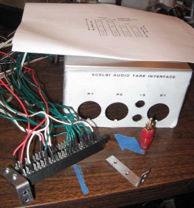
The front has been drilled and punched. Note how I used a printout of the drawing as a template for drilling. I still need to drill a hole on the bottom for visibility of the read board LED and one on the back for access to the read board adjustment pot. I’ll do that after I get the edge connectors installed to make sure the holes line up with the board correctly.
The binding posts that I ended up with fit nicely into a 7/16″ hole, though I’ve seen drawings for others that take a 1/2″ hole. I’m not happy with my workmanship on the edge connector brackets and am going to make another set before installing. One of the downsides of using Amphenol connectors is that once you solder in the wiring, you cannot remove the connectors from the panel. Since the decals will be clear coated, I need to make and install decals, then clear coat the front of the enclosure before installing those connectors.
To save time, I’m going to reuse most of my original, temporary edge connector wiring by cutting the wires to an appropriate length. I will have to remove the connector ends of the wires from the connectors. Then it will be a simple matter of reconnecting the shorter wires, this time with the connectors mounted in the enclosure. I might redo the power and ground connections so both sides of the edge/connector and board get connected.

