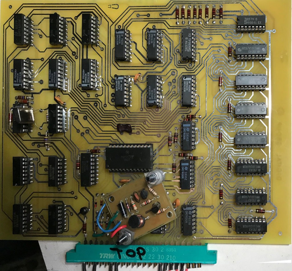
So far, I’ve tested power rails and they appear to be reasonably good. The SCELBI power supplies provide +5 and -9. In addition, components on this card need -5 and +12. The -5 is generated on board using a series of voltage dropping diodes connected to the -9 supply. The +12 is generated with the little converter that can be seen mounted on top of the board. That converter has been documented in a few previous posts. The -5 supply sits at something like 5.6, which is a bit on the high side, but I’ll just go with it. The +12 looks pretty good, as it is sitting at 11.8. Voltages could change a little bit in actual operation as the testing was done without a running clock. I’ll definitely keep an eye on that as I move forward with more testing.

I am expecting the crystal that I need to arrive next week. The installed crystal is something I had on hand in a parts bin. It is something like 3.6 Mhz, which I figured is close enough that I could use it to check clock generation and general performance of the timing portions of the circuit.

Nice!
Could it had been that when they originally made this, they measured the -5V with an analogue multimeter with something like the typical load of 20k ohm / volt and got a slightly lower reading and thought that it would be good enough?
The clock v.s. no clock theory seems more likely though.