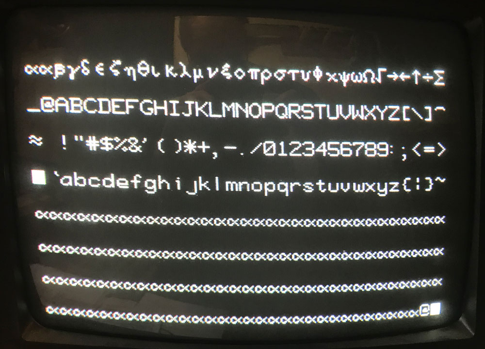
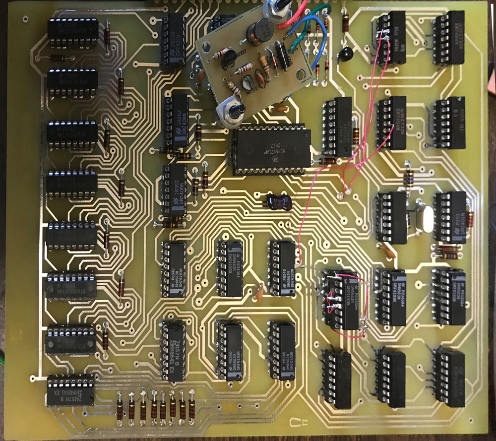
In an addendum to my previous post, I noted that I had MCM6571A instead of regular MCM6571. It seems like the A part is easier to find than the regular part, so I decided to hack the board to support the A part, while I look around for a non-A part. Here’s an example of the resulting video output after the hack.

These parts have the same character set, but the row decoding goes up from 0 to 8 on the A part instead of from 14 down to 6 on the regular part.
Fortunately, on the DG video card, row input to the MCM6571 is entirely from the four outputs from the 74193 at U9. The 74193 supports counting down or up as well as configurable preloads. So all you need to do to support the “A” part is count up instead of down and reconfigure the preload, preload trigger and carry out to the next 74193. This can all be done without extra gates.
The standard DG card counts down from 15 to 2 and then restarts the count using the gate at U-22. To make the circuit work for the “A” part, I choose to reconfigure the counter to count up from 0 to 12. This is one less sweep of horizontal per line of characters, but it doesn’t seems to affect vertical hold on the terminal that I am using and it prevents the last line of text from being too “low” on the screen and puts the lines a little closer together for a slightly more pleasing display.
The carry over to U-10 occurs on the rising edge of the most significant bit of the the counter. This happens when the count goes from 2 (binary 0010) to start over at 15 (binary 1111). To make the circuit work for the “A” part, I choose to use the inverted version of the most significant bit, so it carries over when the output goes from 12 (1100) to 0 (0000).
Here is the wiring list needed to make this change. I choose to put the 74193 in an extra socket to make the rework easier. The way I made this change, it is completely reversible and requires no cuts to the PCB, so when I find a non-A part, I’ll be able to retrofit it to this board with minimal effort.

- Remove the 74193 at U9 from the PCB and insert into a spare 16 pin socket with the following legs lifted:1,4,5,9,10,15
- the following two steps change count down function to count up
- Connect pin 4 of the 74193 to the socket pin 5
- Connect pin 5 of the 74193 to the socket pin 4
- the following step changes the preset from 1111 to 0000
- Connect pins 1,9,10,15 of the 74193 to the socket pin 8
- the following two steps changes the reset from a value to 2 to a value of 12
- On the 7410 at U-22 lift pins 9 and 10
- Connect pin 9 of the 7410 at U22 to U9, pin 7 (it can be connected to a convenient via near the MCM6571 that leads to U9, pin7)
- Connect pin 10 of the 7410 at U22 to U9, pin 6 (it can be connected to a convenient via near the MCM6571 that leads to U9, pin6)
- the last step inverts the carry input to the 74193 counter at U10
- Lift U10, pin 5
- Connect pin 5 of the 74193 at U10 to U17, pin4
Now all I need to do is to get some kind of demo application running and update my Macintosh SCELBI app to support emulation of this new SCELBI capability.
If anyone wants one of these reproduction DG video boards, cost will be $50 each, with free shipping in USA, $10 shipping outside the USA. Send me an email if you are interested.
