The prototype electronics for this probe have only been bench tested. It was inspired by Gary Bishop's design. However instead of using the quad comparator Gary used, I decided to use the LM324 quad op amp as the heart of my design. I used an old National data book, a National linear applications book and a little handbook on op amps available from Radio Shack during my research. If you can still find it, that little book (276-5011a) from Radio Shack is quite good at showing example uses of op amps. I used the LM324 because it does not need a negative power supply. This will allow you to power the whole design, including a 12 volt solenoid from a single 12 volt DC power supply.
This design is comprised of two primary sections, an amplifier and a comparator.
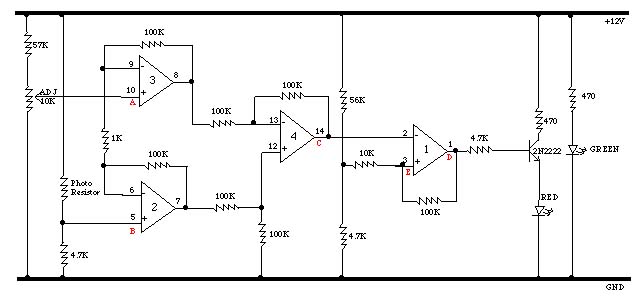
Op amps 2, 3 and 4 are put together like the example DC Instrumentation Amplifier in National's linear applications book. This will amplify the difference between the reference voltage on + input of op amp 3 and the voltage set by the photo resister on the + input of op amp 2.
Op amp 1 is set up to be a comparator of the output of instrumentation amplifier and the reference voltage on the + input of op amp 1. The 100K ohm feedback resistor provides hysteresis to prevent an unstable output condition.
The idea is to adjust the reference voltage input into the amplifier to cause the output of the amplifier to trigger the comparator when the photo resister is getting too much light through the bromothymol blue solution. At that point the output can be used to turn on the solenoid to allow more CO2 into the water.
My design was not completed to the point of driving the solenoid, but I had plans of using a small relay instead of Gary's transistor to drive it. I am not sure what I would do today, if I was to continue the project. The problem with relays is reliability. If you decide to go with this design you will have to figure out the solenoid driver on your own. The transistor used to switch the LED on and off could probably be used to directly drive a relay or solenoid, with few modifications. The design will switch on the LED as the PH goes up (the solution gets darker). For a relay application you would want to use one that was connected as normally open, as engaging the solenoid and releasing CO2 into the tank will lower the PH.
Most, if not all of the components should be available from Radio Shack. I built up the prototype using a Radio Shack bread board, which I find very handy for these sorts of small projects. I had a small bench power supply which I used for my testing. Any small 12V DC power supply should work fine.
Construction of the electronics requires the following components.
| Quantity | Description |
| 7 | 100K resistor |
| 1 | 10K resistor |
| 3 | 4.7K resistor |
| 1 | 56K resistor |
| 1 | 57K resistor - I think a 56K would work just as well in place of this one |
| 2 | 470 ohm resistor |
| 1 | 1K resistor |
| 1 | 2n2222 npn switching transistor |
| 1 | 0-30K photo resistor (radio shack) |
| 1 | lm 324 quad op amp |
| 1 | 15 turn 0-10K trimmer resister |
| 1 | red led |
| 1 | green led |
I measured voltages at points A, B, C, D and E and got the
following
values for on and off. Remember that the values you get will
depend
upon the amount of light reaching the photo resistor and the setting of
the adjustable 10K trimming resistor. Note that the change in
the
input voltage to switch the LED on was only .005 volts in this case.
| ON | OFF | |
| A | 1.153 | 1.148 |
| B | 1.158 | 1.160 |
| C | .86 | 2.047 |
| D | 10.55 | -.033 |
| E | 1.33 | .89 |
Let me know if you try this design and if you encounter any problems or have ideas for improvements.
Back to Mike's Hobby Home Page