Sound Card Shutter Tester
I have implemented a sound port shutter tester, which is described later on this page. However I am disappointed with it's inconsistent performance at higher shutter speeds and the inability to make the HW work on different computers. In order to rectify the situation I've designed a shutter tester that interfaces directly to an old Apple ][ computer, and am much happier with that solution. I highly recommend moving away from the sound card shutter tester to a dedicated HW solution. See my Apple ][ based tester page for the latest on that design or to Optical Timer/Counter page for my latest micro-controller based design.
At the minimum, a calibrated constant light source is needed in order to obtain consistent turn on and turn off signal slopes with this design. I never could get good results at higher shutter speeds, as the results tended to show a slower speed than the the exposure is seen with my new design. If you are having trouble calibrating with this design at high speeds, I would suspect troubles with the sound port shutter tester.
I will not be held responsible for any damage that results from you looking at or following these ideas and designs. If you don't feel comfortable goofing around with this stuff or the possibility that you could damage something on your computer or camera, just don't do it.
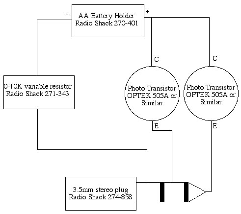
This shutter tester is based on the design at http://www.geocities.com/Yosemite/2131/shspeed.html . I thought that I have enhanced that design in several important ways, when just before posting the design to my website, I found this wonderful site, with a very similar design- http://www.kyphoto.com/classics/combinationtester.html . Having been involved in computer and networking designs for many years, I have come to the conclusion that if you have a novel idea, it is very likely that someone else has the same idea. Looks like I was right, at least in this case.
Anyway here is what I have done to enhance the original design.
Measuring Shutter Curtain Speed
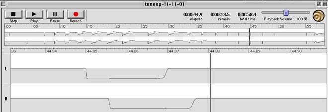
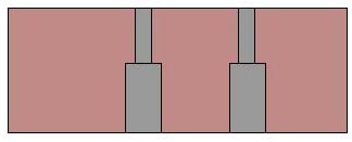
You can measure shutter curtain speed by taking the time difference
between the first and second channels. For instance, in this case, the
second channel trails the first channel by about 5 milliseconds. The distance
between the sensors is about 14 mm. Total time for the curtain to cross
the entire film plane is then 36mm(actual film plane size)/14mm(distance
between sensors) * 5 milliseconds = about 12.8 milliseconds. You can also
tell if the first and second shutters are running at the same speed. The
total exposure times of both channels will be different, if one shutter
is running faster than the other.
Measuring Exposure Time
I measure the exposure time by measuring from the falling edge
of the signal to the time just as it begins to rise. In this case, the
exposure time is about 18 milliseconds, which is a bit long for a true
1/60th of a second.
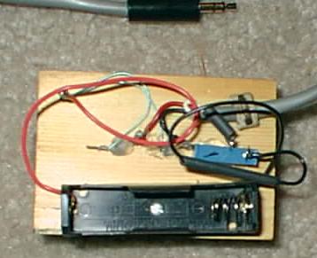
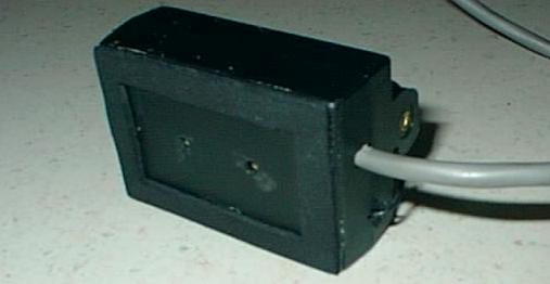
Later, after looking at the cosmetics and realizing that I wanted to document
my efforts on this web site, I decided to package it in a very small
project box. That is pictured here. There is no difference in performance
of the two versions. The project box version uses a smaller block of
wood which has been epoxied to the inside front of the box. I did omit
the stepped drilling of the wood and just seated the transistor in the
smaller hole, since the box was enclosed and the photo transistors would
be protected from abuse. The holes also have been adjusted to 18mm between
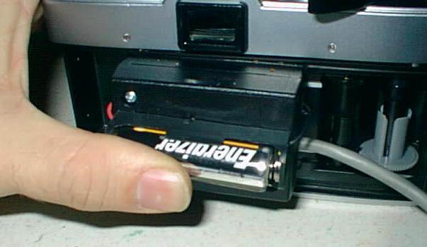
sensors. I left the AA battery on the outside of the box for ease of
servicing. If you wanted too, I'm sure a 1.5 volt N battery would fit
inside the box. I also found some thin, black foam padding at a nearby
department store and used contact cement to glue a rectangle around the
face of the box in order to get a slightly better light seal. At first,
I was going to use some felt padding I found at a Home Store, but I felt
the felt had too much fuzz and was thicker than necessary. I wanted my
sensors to be as close the film plane as was reasonable, without coming
into contact with the shutters, themselves.
Using the Shutter Tester
You simply place the camera in from of a light source, open the
back of the camera and place the sensor where the film would normally
reside when taking a picture. Make sure your shutter tester is plugged into
a line level stereo input jack on your computer, start the capture software
and take one or more "pictures". Stop the capture software and examine
the results. I find my shutter tester works slightly better when I remove
the lens from my SLR camera, but it is not necessary.