Build your own Replica

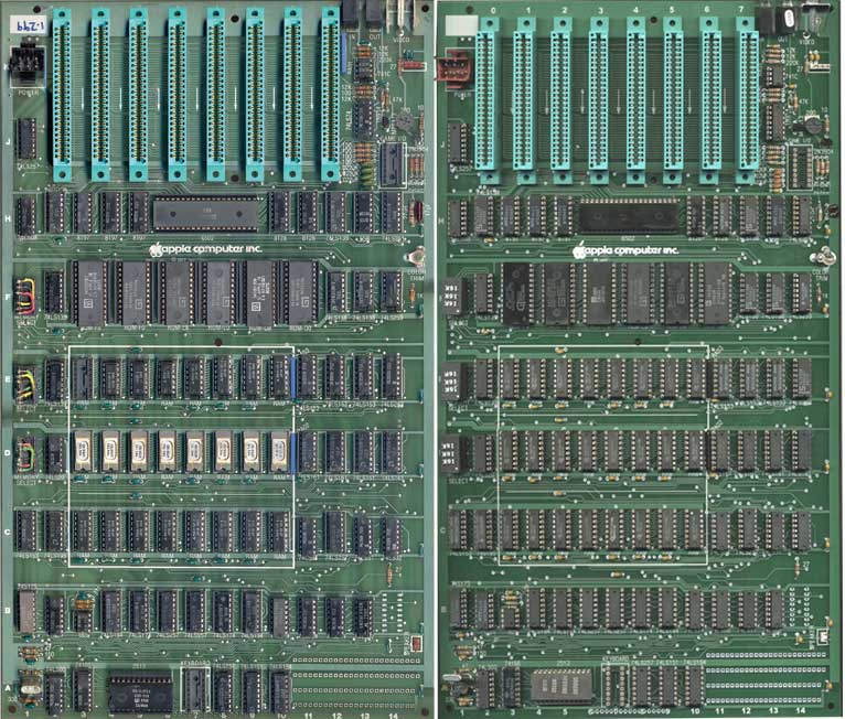
actual Apple II number 1.299 on left, my replica on right
(rev 0 images provided by Geoff Harrison - www.solivant.com)
click here for close-up comparisons of my replica and the original rev 0
Background on the Apple II Rev 0 Replica
The first 6000 or so Apple II's sold, were equipped with what is called a revision 0 motherboard. A number of Apple II motherboards were also sold at the same time without case, keyboard or power supply. Most of these bare board systems were revision 0. One of these early machines was my personal Apple II. At some point, when the machine was on loan to a family member's business, the original rev 0 board failed. It was repaired via replacing the motherboard with a rev 3 board. Over the last few years, I've been working to restore the machine to original condition. In the process, I've spent a long time looking for an appropriate Rev 0 motherboard.
With only 6000 made, rev 0 boards are scare and very expensive when you do see them on eBay. I would hate to buy a complete Apple II with original Rev 0 board, only to separate the board from it's matching case, keyboard and power supply. I needed to find either a bare board or a mismatched machine. After a couple of years of hunting around for a stray rev 0 board, I realized that it would be quite a while before I would find what I was looking for. I decided that I would try to build a replica of a Rev 0 motherboard for my old machine. It seemed like it would be a fun and challenging project. This project also would be a good way to put my machine back into a state closer to original condition. It turned out that I was right on all counts.
What Makes a Rev 0 Board Different
Later revision motherboards were enhanced in several minor and a couple slightly more significant ways. Many of these differences are documented on my PCB layout page. The most significant two changes to later rev boards was the addition of a power-on reset circuit and the addition of two more colors to HI-RES graphics mode. In the end, the power-on reset change was not significant, because all Disk II controllers also included a power-on reset circuit and most all Apple II's eventually were equipped with floppy disk drives with this reset function. Programs that used the additional two colors of the later rev boards are almost always perfectly usable with the rev 0 board. The net result is that rev 0 boards are almost as capable as all later revision Apple II and Apple II plus boards.
Identify an Apple II Rev 0 Motherboard at a Glance

- Look for the large prototyping area from A-11 to A-14 that could be used for add-on circuits. This area is vastly reduced in later rev boards. A significant portion of it was used to make the changes to add the reset and the additional colors in these later boards.

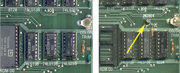
- No transistor near location F-13. A color killer circuit was added to rev 1 and later boards that included a transistor at this location. This transistor was supposed to suppress the color output during text only mode. This change didn't completely kill the color burst signal and depending upon the monitor or TV that was being used, the color still might be displayed in text only mode, even on later rev boards. This transistor can usually be detected even on relatively low resolution images of later rev motherboards.

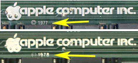
- Copyright 1977 printed under the Apple Computer Inc. logo. This is usually hard to detect in most web images.
Build Your Own Rev 0 Replica
The Saga of the Rev 0 Replica Project
Apple II Rev 0 Evolution
Rev 0 Hardware Mods
- Color Killer (page 6 of Apple's Contact Newsletter - June, 1979)
- Adding Colors
- Byte Magazine Article from June 1979 - found at reactive micro web site - link to article (error in schematic - pin 1 of 74ls74 is missing connection to soft-5 - a2-8)
- Woz Wonderbook, pages 37-41 - found at digibarn.com web site - link to document (note that schematics in this copy are almost illegible)
- My translation of illegible Wonderbook schematics. Also Pin 7 of 74LS02 goes to GND and Pin 14 goes to +5v.
- Note - to avoid damaging or altering your motherboard, the two new chips can be glued upside down on existing chips with hot melt glue rather than be soldered in proto-area. Put the 74ls74 upside down on A-9 and the 74ls02 upside down on B11. Keep in mind that upside down chips have pins on opposite sides of the chip compared to right side up chips.
- Adding Hsync Serrations fo Vsync signal, described in the book, "Understanding the Apple II" by Jim Sather.
- Woz Wonderbook, page 42 - found at digibarn.com web site - link to document (note that this page is almost illegible)
- My translation of illegible Wonderbook schematics
- Adding later rev sync circuitry. The change documented in the Wonderbook turns out to be different than what was added to later rev boards. If you have trouble with distortion at the top of your screen, here is a mod that gets you later rev Hsync and Vsync signalling on a rev 0 board. This mod is something I came up after a replica builder encountered this issue. I have made the mod on one of my boards and tested it. Also mentioned is a much simpler hack that also helps stabilize the picture.
My Apple II restoration pages
Back to Mike's Hobby Home Page